
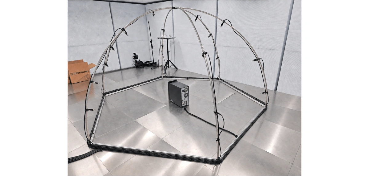
This guide helps users quickly set up and perform sound power testing using a hemispherical sound power test frame, the SonoDAQ Pro data acquisition front-end unit, and OpenTest.
| Stage | Completion Criteria |
| 1. Frame installation | The hexagonal base is stable, the 6 arc tubes are tightened, and the top cover is secured without shaking. |
| 2. Microphone installation | Microphones are installed at the measurement point positions marked on the hemispherical frame. |
| 3. Acquisition front-end connection | The front end is powered on, the Ethernet cable is connected to the computer, and OpenTest can detect the device and channels. |
| 4. Software configuration | Channels, sensitivity, standard method, measurement surface, acquisition duration, and environmental parameters are configured. |
| 5. Complete test | Calibration, background noise acquisition, DUT operating noise acquisition, result review, and report export are completed. |
1. Unpacking and Pre-Installation Check
- Check that all parts are included: 6 base square tubes, 6 arc tubes, 1 top ring/top cover assembly, microphone fixing clamps and positioning plates, M5 screws, M3 thumb screws, and an Allen key.
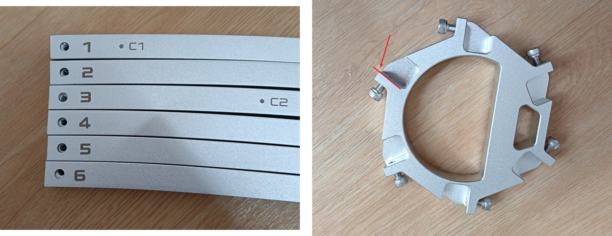
- Check whether the numbers 1, 2, 3, 4, 5, and 6 on the ends of the arc tubes are clearly marked. These numbers are used for the subsequent paired installation.
- Check whether the point markings on the arc tubes are clear. Point A is used for the survey method, Point B for the engineering method, and Point C for the precision method.
- Select a flat, rigid, and stable reflecting surface for installation. A semi-anechoic chamber floor or a standard reflecting floor is preferred.
- Clear the installation area first. Make sure there are no cables, foam, tools, or uneven pads under the frame base.
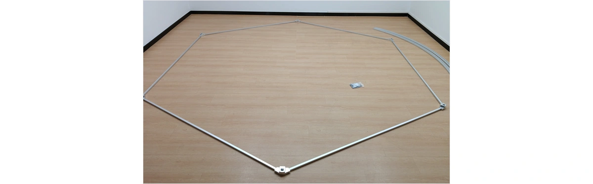
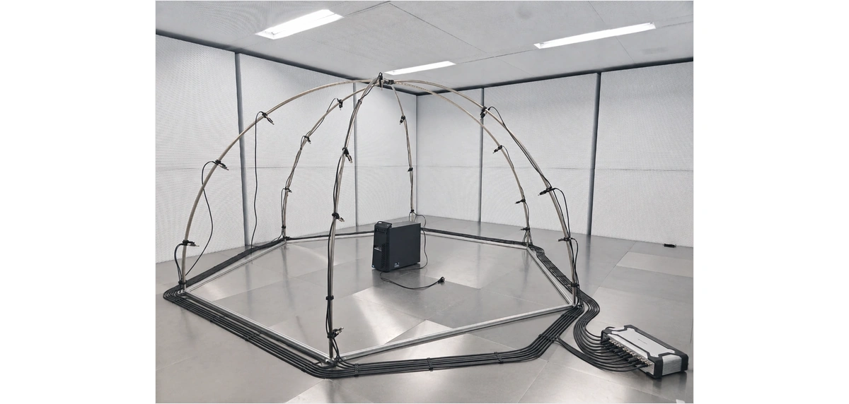
2. Assemble the R1.5 m Hemispherical Sound Power Frame
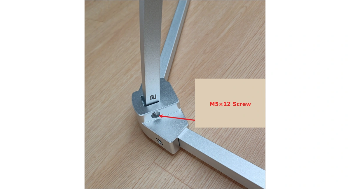
- Assemble the hexagonal base. Take one straight square tube and one base connector, align Hole 1 and Hole 2, and secure them with an M5*12 screw.
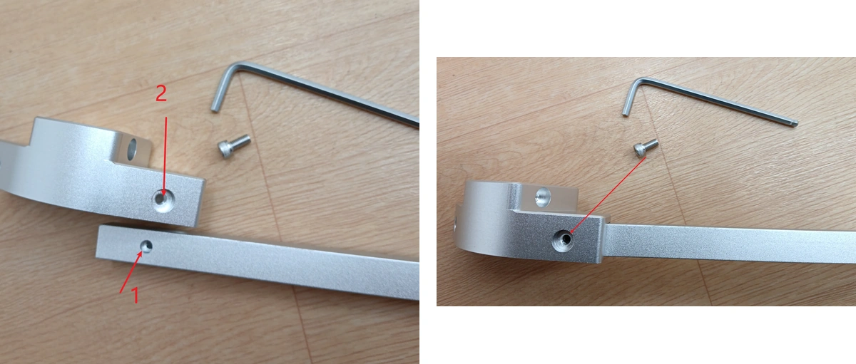
- Install the remaining five square tubes in the same way to form a complete hexagonal base. Before tightening, make sure the hexagon is not visibly twisted.
- Pre-install the top ring/top cover. Insert six M5*12 screws into the top cover first, but do not let the screws protrude beyond the end face of the top cover, otherwise they may interfere with arc tube insertion.
- Install Arc Tube 1 first. Insert Arc Tube 1 into one of the base holes.
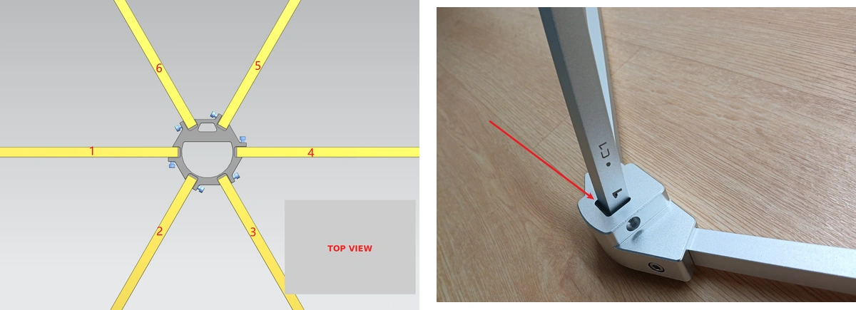
- Then install Arc Tube 4. Insert Arc Tube 4 into the base hole opposite Arc Tube 1.
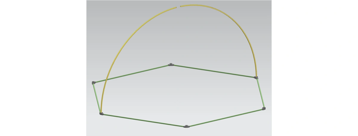
- Connect the top cover to Arc Tubes 1 and 4. Align the screws with the holes on the arc tubes, and tighten positions 1 and 4 first.
- Install Arc Tube 2, insert Arc Tube 5 into the base hole opposite Arc Tube 2, and then tighten them.
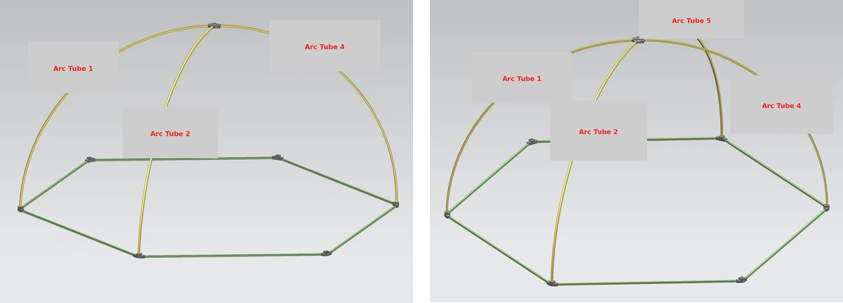
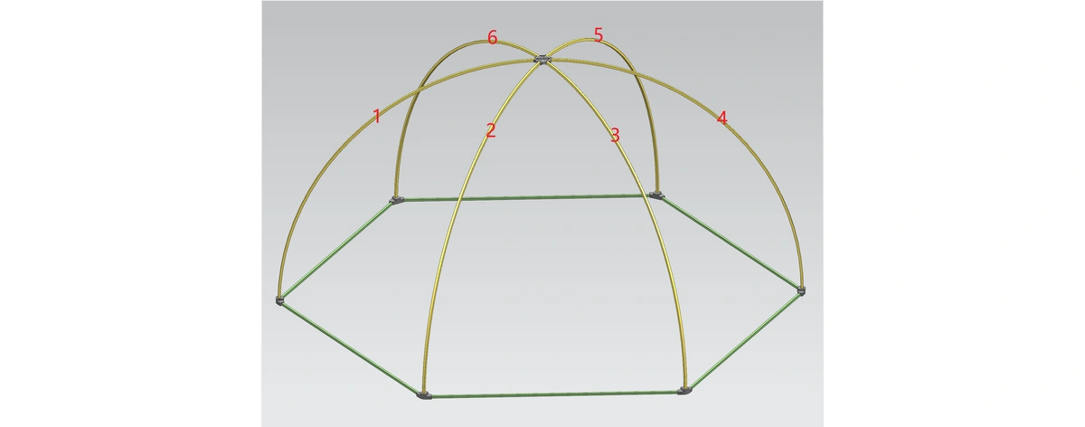
- Install Arc Tubes 3 and 6 in the same way.
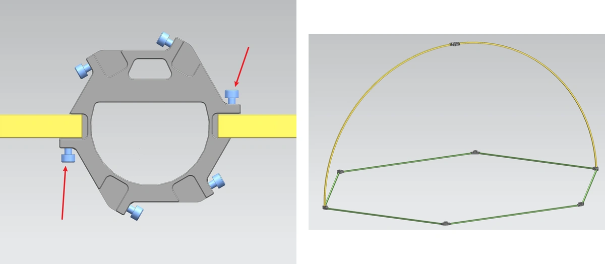
- Insert and tighten an M5*12 screw on the side of the base. Tighten the other five base positions in the same way.
| Frame Check All arc tubes should naturally form a hemisphere and should not be forced or twisted to align with holes. The center of the top cover should be at the top of the hemisphere, and the base should fully contact the floor. Gently push the frame by hand; there should be no obvious shaking or looseness. |
3. Install Microphone Clamps and Measurement Points
Point markings are distinguished by test method:
| Point Marking | Corresponding Method | Number of Points |
| A1-A4 | Survey method | 4 points |
| B1-B10 | Engineering method | 10 points |
| C1-C20 | Precision method | 20 points |
- Select the points according to the test method used. For example, for the engineering method, select B1-B10, and match the microphone numbers to the point numbers in sequence.
- Take the microphone fixing clamp and positioning plate, gently hold the positioning plate by hand, and use the Allen key to tighten an M5*12 screw.
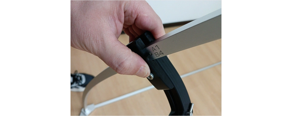
- Align the small raised point on the positioning plate with the marked circle on the arc tube, then tighten it.
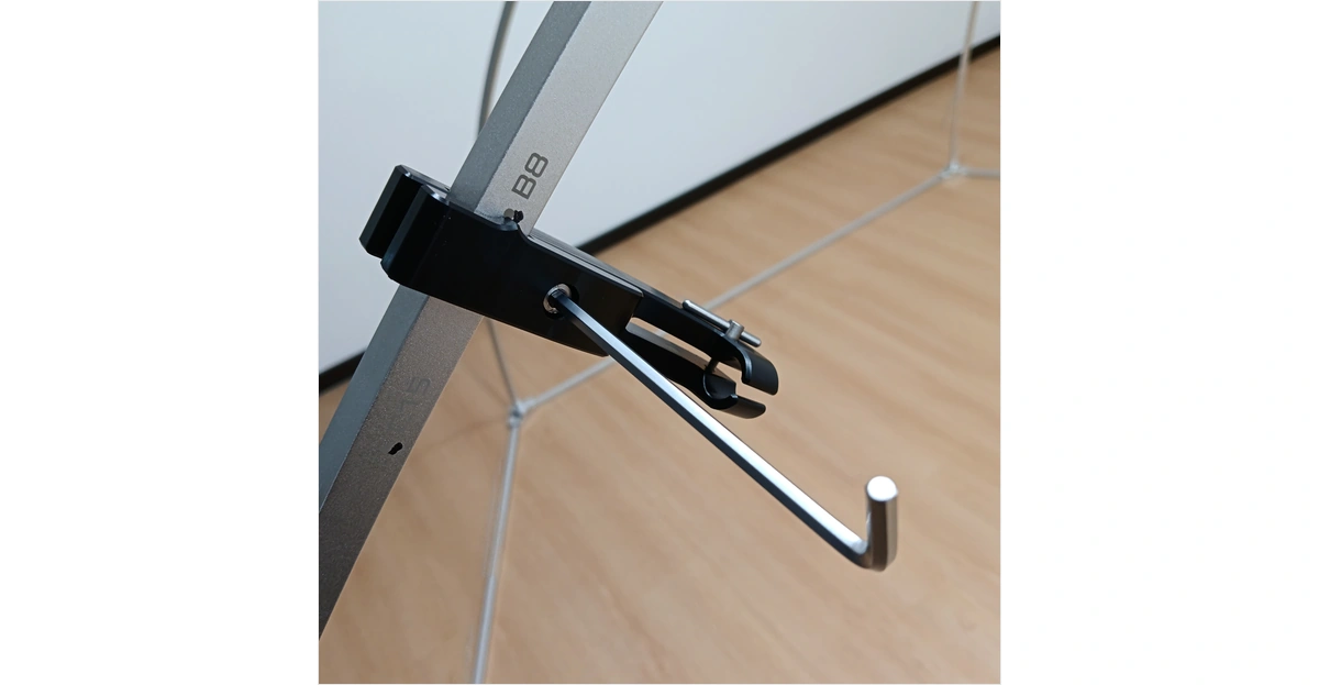
- Install the other points in the same way. If the survey method and engineering method share the same point, install it according to the frame marking; duplicate installation is not required.
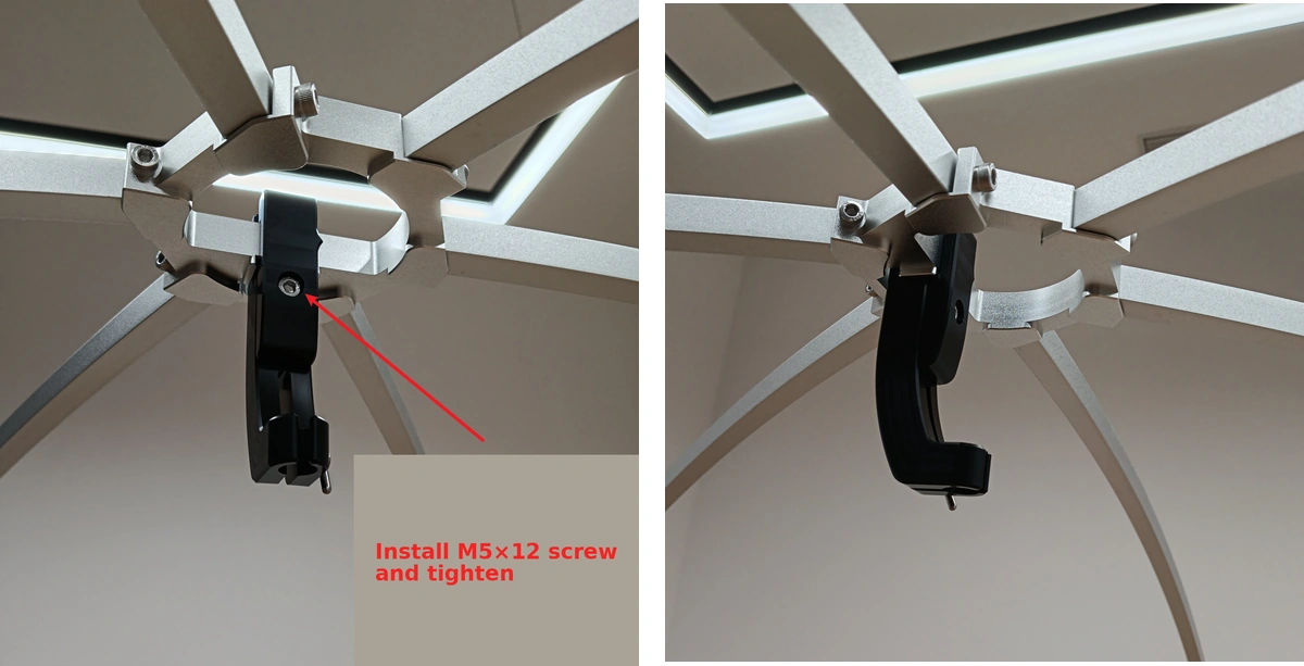
- When installing the top microphone bracket, align the center of the clamp with the center of the top cover, insert an M5*12 screw, and tighten it.
4. Install Microphones and Cables
- Gently place the microphone or microphone preamplifier into the clamp, avoiding any impact on the microphone diaphragm.
- Adjust the microphone position so that the distance from the microphone end face to the clamp end face is approximately 29 mm.
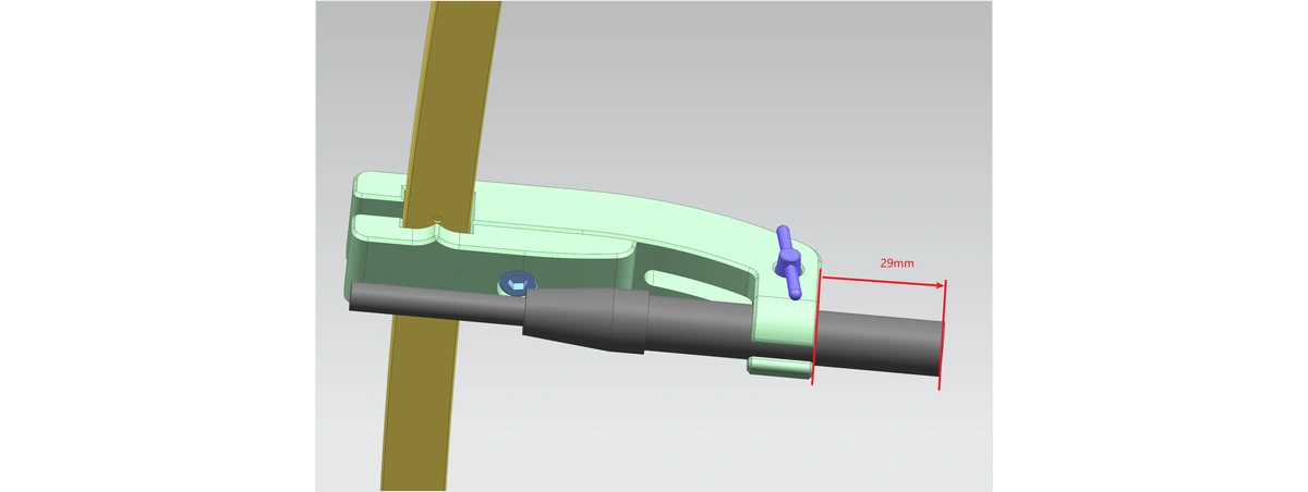
- Secure the microphone with the M3 thumb screw. Tighten it only until the microphone no longer slides; do not overtighten.
- Connect cables according to the point numbers. For example, B1 corresponds to CH1 and B2 corresponds to CH2. It is recommended to attach the same number label to both ends of each cable.
- Route the cables along the outside of the frame or toward the base. Avoid suspended cables pulling on the microphones, and do not allow cables to enter the main sound propagation path between the device under test and the microphones.
- After all microphones are installed, check each point for position, orientation, cable number, and fastening status.
5. Power On and Connect the Data Acquisition Front-end Unit
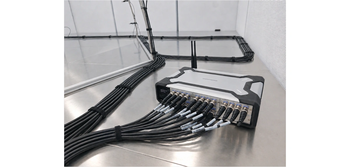
- Place the SonoDAQ Pro or the corresponding multi-channel data acquisition front-end unit outside the frame. Keep it well ventilated and avoid placing it between the device under test and the microphones.
- Connect the microphone cables to the input ports of the acquisition front end according to the channel numbers. Do not pull on the cable connector ends during connection.
- Connect the power supply to the acquisition front end. After confirming stable power, switch it on and wait until the status indicator shows normal operation.
- Connect the acquisition front end to the computer using an Ethernet cable or another supported connection method. If using Ethernet, confirm that the computer network adapter and the device can communicate.
- Open OpenTest, go to Device Management or Channel Management, then search for and add the acquisition device.
- In Channel Management, select the input channels required for this test and set the signal type, sensitivity, sampling rate, bit depth, coupling mode, and power supply mode for each channel.
| Channel Configuration Reminder Microphone sensitivity should come from the calibration certificate, TEDS, or on-site calibration results. Channel numbers must match the frame point numbers. This is the basis for subsequent calculation and review. |
6. Pre-Test Calibration
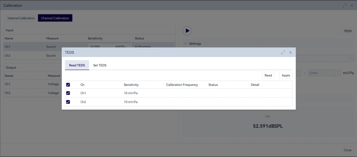
- In OpenTest Channel Management, enter the calibration function and select microphone calibration.

- Attach the sound calibrator to Channel 1 microphone and set the calibration sound pressure level and frequency, such as the commonly used 94 dB and 1 kHz. Use the nominal values of the calibrator as the reference.
- Start calibration and wait for the software to provide the sensitivity or calibration result.
- Calibrate all microphone channels one by one using the same method.
- If TEDS-supported microphones are used, the microphone sensitivity can also be read directly from TEDS in OpenTest.
- After calibration, record the calibration time, calibrator model, calibration sound pressure level, frequency, and the result for each channel. For formal tests, pre-test calibration and post-test verification are recommended.
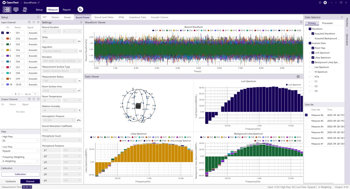
7. Create a Sound Power Test in OpenTest
- Create or open a project, then go to the Sound Power module under the measurement functions.
- Select the calibrated microphone channels as the input channels.
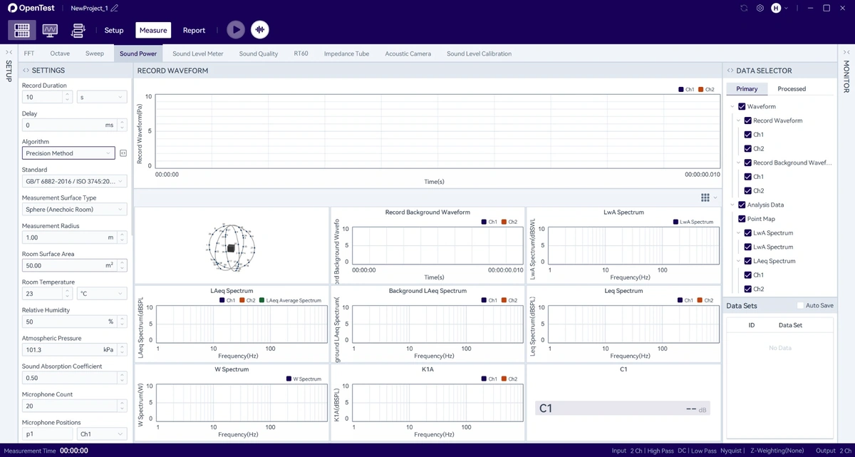
- Select the test method and standard: the survey method corresponds to GB/T 3768 / ISO 3746, the engineering method to GB/T 3767 / ISO 3744, and the precision method to GB/T 6882 / ISO 3745.
- Select the measurement surface. For an R1.5 m hemispherical frame, a hemispherical measurement surface is usually selected. For semi-anechoic chamber tests, select the hemispherical measurement surface in a semi-anechoic chamber or the corresponding hemispherical measurement surface.
- Enter the measurement radius.
- Enter the number of microphones and confirm that the number of measurement points in the software matches the actual installed points.
- The microphone numbers in the software must correspond to the installed point numbers.
- Enter environmental parameters, including room temperature, relative humidity, air pressure, room area, sound absorption coefficient, and other required values.
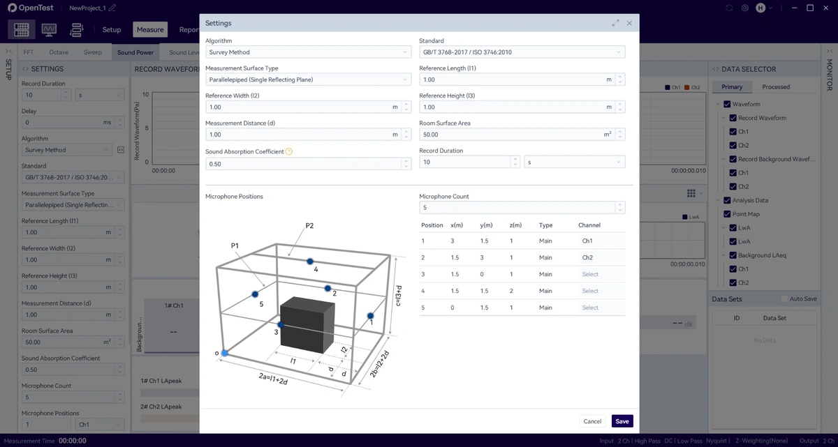
- Set the acquisition duration, frequency weighting, frequency range, time weighting, calculation parameters, and other settings.
8. Place the Device Under Test
- Place the device under test in the central area of the hemispherical measurement surface, ensuring that the measurement surface fully encloses the sound source.
- Connect the power supply, network cable, load, air duct, or fixtures for the device under test according to the test plan. Cables should be routed close to the floor or along the outside of the frame whenever possible.
- Confirm the operating condition of the device under test, such as idle, typical load, full load, fixed speed, or a specified mode.
- If the device requires warm-up or load stabilization, wait until the operating condition is stable before starting acquisition.
- During the test, personnel should leave the measurement area as much as possible to avoid human-body reflections and additional noise affecting the results.
9. Acquire Background Noise
- Turn off or stop the device under test and keep the laboratory in the same background condition as during the formal test.
- In the OpenTest Sound Power module, click background noise acquisition.
- During acquisition, check whether the background LAeq or 1/3-octave background noise spectrum of each channel is abnormal.
- If the background level of a channel is obviously high, first check the microphone, cable, interface, and nearby noise sources for that channel.
- After background noise acquisition is complete, save the record before proceeding to DUT operating noise testing.
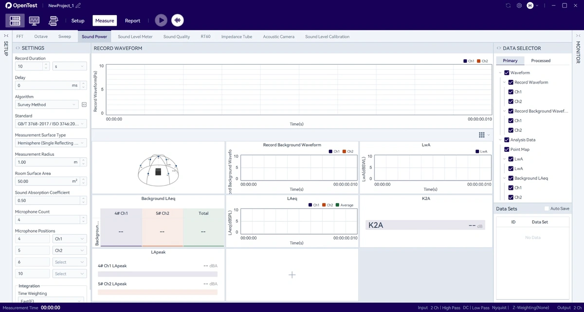
10. Acquire DUT operating noise and Calculate Sound Power
- Start the device under test and confirm that the operating condition meets the test requirements.
- Start the sound power test in OpenTest. The software will run for the preset acquisition duration, or it can be stopped manually.
- Monitor real-time data during the test. The survey method usually focuses on LAeq for each channel, while the engineering and precision methods should also include 1/3-octave data.
- After the test, review the calculated results, including LA, LAeq, LWA, background noise LAeq, K1A, K2A, sound power spectrum, LWA spectrum, and other values.
- If the software indicates that background noise was not acquired, channel data is missing, or the result is abnormal, return to the corresponding step for troubleshooting first.
- If repeatability needs to be verified, keep the operating condition unchanged and repeat the acquisition 1-2 times, then compare LWA and the main frequency-band results.
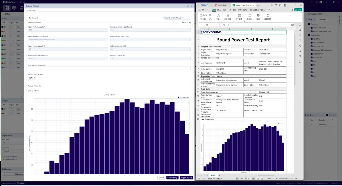
11. Save Data and Export the Report
- In Data Sets, confirm that the background noise and DUT operating noise records for this test have been saved.
- If raw waveforms need to be retained, export .wav files. If post-processing or review is required, export analysis data in .csv format.
- Click the report function and fill in the project information, sample information, equipment information, test description, and test standard.
- Select the test record and confirm that the report includes the measurement point layout, background noise, LWA, spectrum results, and necessary correction quantities.
- Export the Excel report and convert it to PDF or archive it according to customer or laboratory requirements.
12. Shutdown and Storage
- Stop the device under test and close the current test in OpenTest.
- If post-test calibration verification is required, complete the verification before removing the microphones.
- Switch off the acquisition front end, then unplug the microphone cables and computer connection cable.
- When removing a microphone, loosen the fixing screw first, remove the microphone, and install the protective cap.
- If the frame needs to be disassembled, follow the reverse installation order: microphone clamps first, then the top cover and arc tubes, and finally the base.
- Count the screws, clamps, cables, and tools, and store them according to their numbers.
13. Quick Troubleshooting
| Issue | Check First |
| OpenTest cannot find the acquisition front end | Confirm that the front end is powered on, the Ethernet cable/USB is connected, the computer network adapter is normal, and the device and computer can communicate. |
| No signal on one channel | Check the microphone, cable, interface, whether the channel is enabled, power supply mode, and sensitivity setting. |
| Calibration fails | Check the calibrator battery level, calibrator output value, whether the microphone is firmly inserted, and whether the channel range is suitable. |
| Background noise is too high | Check air conditioning, fresh air systems, computer fans, personnel activity, doors/windows, external construction, or noise from other equipment. |
| Large fluctuation in LWA results | Check whether the operating condition of the device under test is stable, whether microphone positions are loose, and whether background noise is close to DUT operating noise. |
| Report data is incomplete | Confirm that both background noise and DUT operating noise have been acquired and saved, and that the correct test record is selected in the report. |
NEW
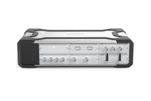
CRY5810 SonoDAQ LT
lsolation
1000 V
Channel
24 channels per mainframe
Interface
USB-C / Ethernet
NEW
$1,549.99
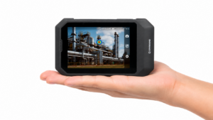
CRY8024 SonoCam Pocket Acoustic Camera
Mic Array
64 channels
Frequency
2kHz ~ 65kHz
SPL
28 dB ~ 132 dB
NEW

OpenTest
Mode
Measure Mode, Analysis Mode, Sequence Mode
Monitor
Scope, FFT Spectrum, Spectrogram,RMS Level, DC Level, Peak Level, THD Ratio, THD+N Ratio, Crosstalk, etc.
Measure
FFT Analysis, Octave Analysis, Continuous Sweep, Stepped Frequency Sweep, Sound Power Testing, Sound Level Meter, Sound Quality, etc.
NEW
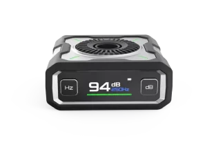
CRY3018 Sound Calibrator
Frequencies
1000 Hz, 250 Hz
Sound Pressure Levels (SPL)
94 dB / 114 dB
Compliance Standard
IEC 60942:2017 Class 1
NEW
CRY5810 SonoDAQ LT
lsolation
1000 V
Channel
24 channels per mainframe
Interface
USB-C / Ethernet
NEW
$1,549.99
CRY8024 SonoCam Pocket Acoustic Camera
Mic Array
64 channels
Frequency
2kHz ~ 65kHz
SPL
28 dB ~ 132 dB
NEW
OpenTest
Mode
Measure Mode, Analysis Mode, Sequence Mode
Monitor
Scope, FFT Spectrum, Spectrogram,RMS Level, DC Level, Peak Level, THD Ratio, THD+N Ratio, Crosstalk, etc.
Measure
FFT Analysis, Octave Analysis, Continuous Sweep, Stepped Frequency Sweep, Sound Power Testing, Sound Level Meter, Sound Quality, etc.
NEW
CRY3018 Sound Calibrator
Frequencies
1000 Hz, 250 Hz
Sound Pressure Levels (SPL)
94 dB / 114 dB
Compliance Standard
IEC 60942:2017 Class 1


