CRYSOUND POCKET Acoustic Imaging Camera Now Available on Kickstarter.

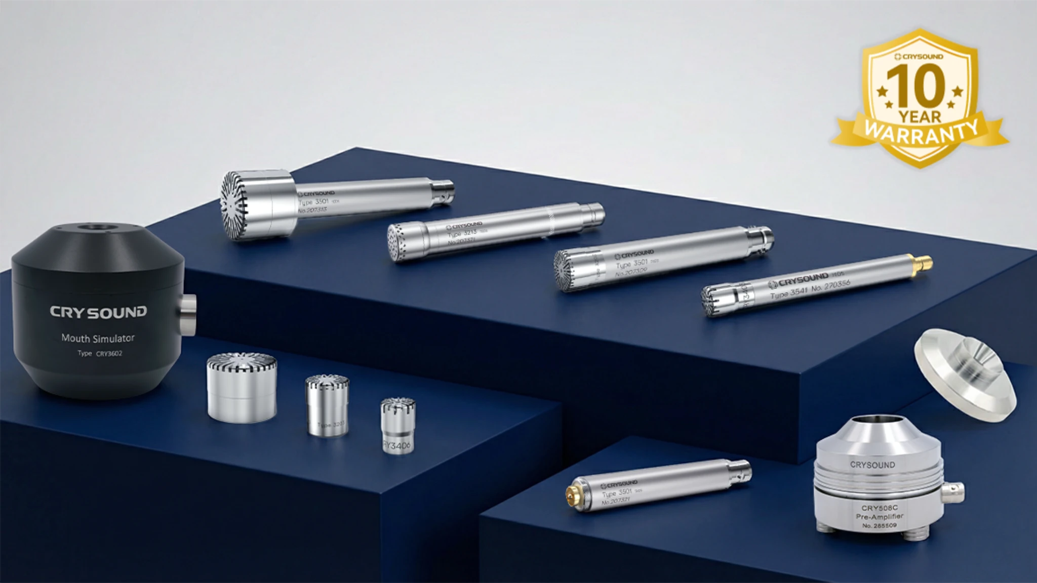
As the core component of measurement chains, the long-term stability of measuring microphones directly impacts the comparability and traceability of measurement data. The 10-year limited warranty (hereinafter referred to as the 10-year warranty) is not merely a service commitment, but a comprehensive capability demonstrated through manufacturing consistency control, reliability verification systems, and traceable evidence chains. This article will outline the engineering implementation approach to explain the rationale behind CRYSOUND's 10-year warranty, and evaluate the impact of this warranty strategy on user lifecycle costs (including maintenance, logistics, downtime, and management costs) based on the Total Cost of Ownership (TCO) framework.
Economic Value of 10-year Warranty: Budgeting Life Cycle Risk Cost
For both laboratories and production lines, the "cost" of microphones constitutes only a fraction of total expenses. The bulk of costs stems from project downtime, retesting and rework, temporary replacements, cross-regional repairs, and administrative complexities. When the warranty period covers a larger portion of the equipment's service life, users can plan risks and resources more clearly within lifecycle budgets. This is the true value of a Ten-Year Warranty.
Engineering Foundation of 10-year Warranty: Reliability Design, Manufacturing and Verification System
Manufacturing Process Capability and Consistency Control: Raw Material Validation and 102 Critical Processes
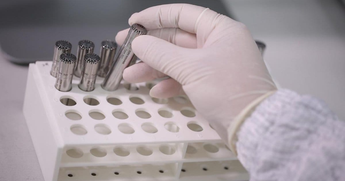
Long-term stability primarily stems from consistency. CRYSOUND begins with raw material validation, preemptively identifying and eliminating risks such as corrosion resistance and insulation stability during the incoming material stage. Subsequently, each measuring microphone must undergo 102 stringent processes, with real-time monitoring during precision machining to ensure consistency in critical dimensions and fit.
Selection of Critical Materials and Assembly Process Control: Physical Basis of Long-term Stability
Key components are assembled by experienced technical experts, utilizing materials with high insulation and low temperature sensitivity to enhance environmental stability. As the core acoustic structure, the third-generation titanium diaphragm technology emphasizes performance objectives such as wide frequency response, high sensitivity, corrosion resistance, and magnetic insensitivity, employing structural and material design to mitigate long-term drift risks.

Typical Failure Mechanism and Verification Coverage Matrix
The long-term stability of microphones is typically compromised not by a single factor, but by cumulative effects of humidity, temperature, mechanical shocks, and contamination, leading to performance drift or noise degradation. Below is a comparison table illustrating how CRYSOUND maps these typical risks to manufacturing control points and factory verification:
| Typical risk/failure mode | Engineering control point | Corresponding Verification / Screening |
| Moisture causes noise to rise sensitivity fluctuation | Clean Assembly,Insulation Design and Process Control | High humidity prolonged test, insulation-related verification (sensitivity pre/post difference / base noise variation / insulation stability) |
| Temperature change-induced drift | Materials and structural stability, assembly consistency | Long-term temperature cycling (sensitivity/frequency response changes, noise trends, structural and connection stability) |
| Structural deflection caused by drop/vibration | Structural strength and assembly process | Drop test, bidirectional vibration test (function output stability, key index difference before and after, structural integrity) |
| Pollution/Particulate Matter Causes Noise Degradation | Ultrasonic cleaning, cleanroom commissioning | Comprehensive factory noise/performance testing (including noise floor, sensitivity, frequency response consistency, etc.) |
| Corrosion/salt spray leads to reduced appearance and connection reliability | Corrosion-resistant Material Screening, Surface Treatment and Connector Protection Design | Salt spray exposure/retention + Appearance and connection reliability verification |
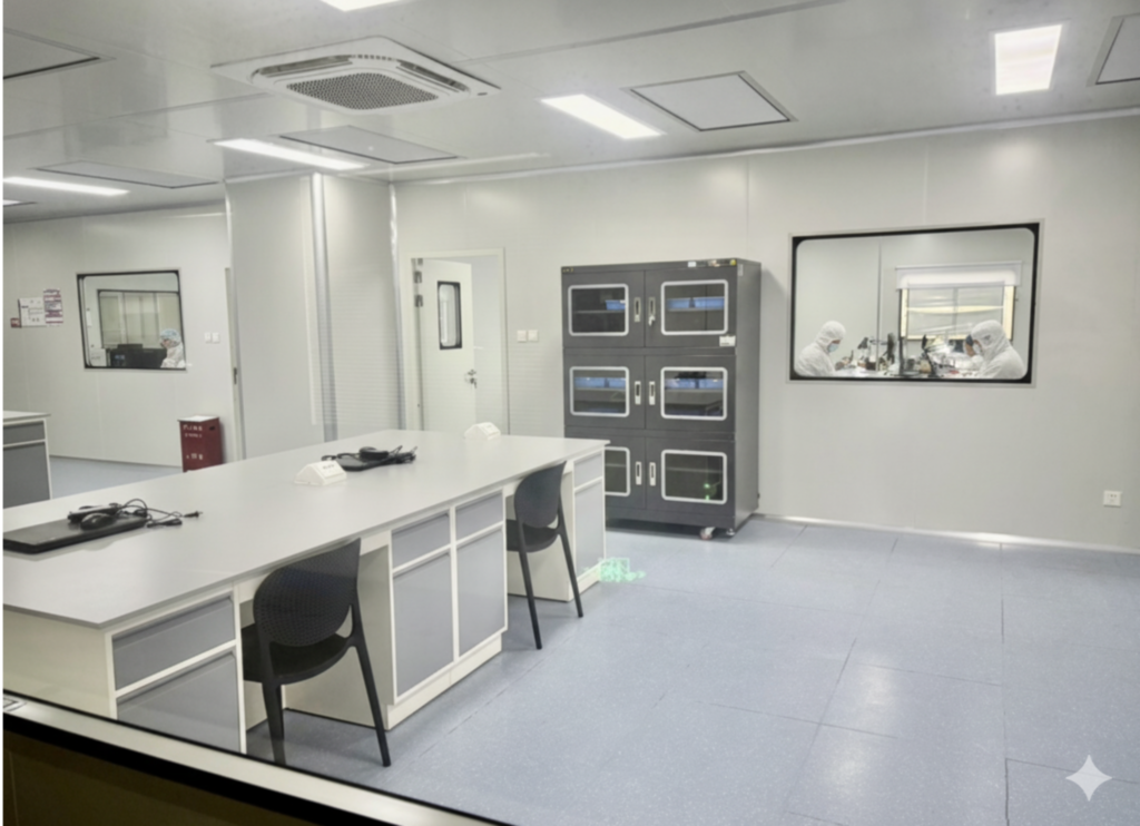
Clean Manufacturing and Pollution Control: Noise and Long-term Stability
Fine particles, oil contaminants, and impurities can amplify into noise elevation or performance fluctuations during prolonged use. To mitigate this, each measuring microphone undergoes ultrasonic cleaning and precision calibration in a cleanroom environment, thereby reducing the risk of contamination and foreign object introduction, ensuring low-noise and moisture-resistant performance at the source.
Factory Reliability Verification Scheme: Environmental/Mechanical/Electrical Stress Verification
A decade-long warranty hinges on systematic coverage of typical service environments and operational conditions. CRYSOUND's factory reliability verification adopts a fundamental approach of "representative environmental and mechanical stress coverage + critical risk coverage," categorizing verification items into three types: environmental stress (humidity, temperature cycling, salt spray), mechanical stress (drop/impact/vibration), and electrical reliability (insulation and leakage risks). This system screens and validates material, assembly, and connection weaknesses through stress coverage of humidity, temperature cycling, salt spray, and drop/vibration conditions before delivery, thereby reducing on-site failure risks.
The high-humidity long-term validation examines how humidity affects microphone performance. Under controlled high-humidity conditions, the device undergoes continuous exposure to simulate prolonged moisture exposure, covering risks like insulation degradation, noise performance changes, and stability fluctuations. This is followed by retesting and electrical status verification to confirm the product's stability and consistency under thermal-humidity stress.
High and Low Temperature Cycling Validation addresses structural and assembly robustness risks under temperature variation conditions. By conducting prolonged cycles between extreme temperature extremes, it accelerates exposure to potential issues including material thermal expansion differences, stress release, and joint stability. The engineering objective of this validation is to assess performance drift risks and connection/assembly stability under long-term temperature disturbances, thereby reducing the probability of post-delivery anomalies triggered by thermal stress.
Salt spray testing addresses material and joint reliability risks in coastal, high-salt, or corrosive environments. By exposing components to controlled salt spray conditions, it evaluates the corrosion resistance of metal parts, joints, and protective designs. The process also includes visual inspection of joints and functional/electrical verification, effectively mitigating corrosion-induced reliability degradation and long-term stability risks.
Note: Salt spray validation is used to evaluate the robustness of protection and connection under typical exposure conditions. For long-term operation in harsh environments such as strong corrosion or high salt spray conditions that exceed the product's usage specifications, additional protection measures must be implemented, with the warranty terms as the ultimate reference.
Mechanical stress verification (Drop/vibration/Shock) addresses mechanical disturbance risks during transportation, installation, disassembly, and field operation. It involves simulating repeated 1-meter drop handling and accidental impacts through specified cycles, replicating transportation vibrations and prolonged mechanical disturbances via continuous vibration tests, and assessing transient stresses under higher intensity through impact validation. The core objective of mechanical verification is to screen structural integrity, assembly stability, and connection reliability, thereby reducing post-delivery risks of intermittent anomalies and performance variations caused by micro-loosening, connector stress, or assembly misalignment.
As a baseline control for electrical reliability, insulation verification addresses risks of leakage, breakdown, or instability caused by moisture, pollution, and material aging. It verifies the insulation performance of critical electrical paths and, when necessary, conducts post-stress environmental reviews to ensure the product maintains stable electrical safety and signal reliability throughout its lifecycle.
All aforementioned validation items are implemented in accordance with the company's internal factory inspection specifications, accompanied by procedures for anomaly isolation, re-inspection, and disposal. Products identified with anomalies during the validation process will not proceed to the delivery phase.
CRYSOUND 10-year warranty key points
| Main points | Explanation |
| Scope of application | Applicable to 3000 series: microphones, preamplifiers, kits, dummy mouthpieces, dummy earpieces, and complete sets (traceable via nameplate/serial number). |
| Warranty Duration Differences | The main equipment typically has a lifespan of ten years; accessories/consumables (such as wind shields, cables, connectors, seals, etc.) have a lifespan of six months and should be separately included in the maintenance budget. |
| Start method | Priority is determined by the outbound/delivery date; if no voucher is available, by the end user's purchase date; if still unavailable, by the last date traceable by the factory date or serial number. |
| Warranty content | Confirm material or process defects: Free repair (necessary parts + labor) or replacement with the same model/performance equivalent to the original (possibly certified refurbishment/remanufacturing). |
| Typical non-protection | Misuse/abuse, drop and compression, liquid immersion, corrosive gases/salt spray, overvoltage/reverse connection/ESD/surge, unauthorized disassembly/repair, etc. |
| Calibration aperture | Calibration drift within the specified range is a common phenomenon in metrology and does not constitute a manufacturing defect; calibration/recalibration is typically a paid service (unless the drift is confirmed to be caused by a manufacturing defect). |
| Logistics and Cross-border | Default rule: Users within the warranty scope are responsible for round-trip shipping costs. Cross-border transactions may incur tariffs, customs clearance fees, or taxes, which are typically borne by the user unless otherwise agreed in the contract. |
Visit https://www.crysound.com/warranty for more information
How A Ten-Year Warranty Affects TCO: Cost Structure and Budget Strategy
TCO scope and boundary conditions
The TCO (Total Cost of Ownership) discussed herein refers to the "total cost" of equipment throughout its lifecycle, encompassing not only the purchase price but also measurement and maintenance, logistics turnover, downtime, and management costs. It is crucial to clarify that warranty coverage addresses "failure risks caused by material/process defects," while calibration/recalibration focuses on "measurement traceability and drift management." Unless testing confirms drift stems from manufacturing defects, calibration/recalibration and measurement certificate updates are typically not covered by free warranty. Users should budget for these as annual predictable costs.
Meanwhile, logistics and cross-border costs related to repairs/services should be factored into the TCO calculation upfront. By default, users are responsible for round-trip shipping within the warranty period. Cross-border transactions may incur tariffs, customs clearance fees, or taxes, which are typically borne by the user unless otherwise stipulated in the contract.
TCO cost decomposition model and accounting subject
A simple model can help you understand the lifecycle cost of a microphone.
TCO = Procurement cost + Calibration/recalibration cost + Logistics/cross-border cost + Consumables and accessories replacement + Unplanned downtime/re-testing/rework + Management cost (ledger/compliance/traceability)
The Impact of 10-year Warranty on Risk-related Costs: Emergency Expenditure Reduction and Management Cost Optimization
Cost reduction for unplanned maintenance/replacement: Material/process defects triggering repairs or replacements are covered by the warranty mechanism, reducing the likelihood of unexpected expenses and emergency procurement.
Reduced downtime and retest/rework costs: With enhanced equipment stability and manageable risks during the warranty period, projects experience fewer instances of temporary failures, abnormal fluctuations, or the need for downtime, retesting, or rework.
Reduced diagnostic and communication costs: Serial number traceability, historical data, and certificate records can lower localization costs, minimize unnecessary back-and-forth and redundant testing, and enhance processing efficiency.
Projected operating costs: annual budget proposal
Calibration/Recalibration (annual budgeting recommended): Minor drift in measuring instruments is normal. It is recommended to calibrate at least once every 12 months or as required by the system; verification or recalibration should be performed after high humidity, high temperature, strong vibration, or frequent disassembly and assembly.
Supplies/Consumables (replenishment budget recommended): Windproof covers, cables, seals, etc. should be procured according to consumables regulations and replacement cycles to avoid downtime and temporary procurement costs caused by 'small components'.
Logistics/International (budget should be allocated separately by scenario): By default, round-trip shipping costs, international customs duties, and clearance fees should be included in advance, especially for multi-location projects and cross-border scenarios.
10-year TCO estimation template
Use the table below to quickly build your TCO estimate for procurement or asset inventory:
| Cost element | Input/Assumption | Notes (How to be affected by the 10-year warranty) |
| Equipment procurement | Quantity, Unit Price (RMB per unit) | Procurement price is not the whole picture, but it determines the asset baseline |
| Annual calibration/recalibration | Frequency (times/year), per-visit cost (yuan) | Typically paid; recommended at least once every 12 months |
| Attachments/Supplies | Replacement cycle and unit price | Plan according to the 6-month/consumable rule |
| Logistics/International | Round-trip freight, customs duties and clearance | The default user assumes responsibility; cross-border scenarios require a separate listing |
| Downtime cost | Cost per outage, annual occurrences | Reliability Improvement and Quality Assurance to Reduce the Probability of Unplanned Outages |
| Retest and rework | Single rework cost, annual occurrence | Performance and Stability Reduction,Rework and Controversy Cost |
Accompanying Management of 10-year Warranty: Usage, Calibration and Asset Ledger
Asset ledger and traceability information management: serial number-certificate-data association
- Enter the serial number and model (photograph for archiving), and bind the calibration certificate with factory data.
- Record critical operating conditions: temperature and humidity, presence of strong vibrations, and frequency of disassembly and assembly.
- When an exception occurs, prioritize reproducing the standard steps and retaining records (screenshots, waveforms, or comparison data).
Usage and Handling Guidelines: Reducing Non-Guarantee Risks
- Avoid drops, compression, liquid immersion, and corrosive environments; power supply and connections shall be performed in accordance with the instructions.
- Unauthorized disassembly and repair are strictly prohibited. Ensure the nameplate/serial number is clearly identifiable.
- Use the original packaging or equivalent protective measures during repair/reinspection, and install protective covers/dust caps on precision interfaces.
Repair Information List: Shorten the Location and Processing Cycle
- Model and serial number photos; purchase/delivery certificates.
- Fault description (scenario, frequency, environmental conditions, power supply and connection method).
- Reproducible test records (frequency response, sensitivity, noise, distortion, or system screenshots/waveforms).
Conclusion: Ten-year warranty engineering logic and user value
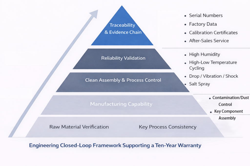
The ten-year warranty is built upon a verifiable, traceable, and operational engineering closed loop: reducing consistency risks through manufacturing process capability control, covering typical failure scenarios via environmental and mechanical stress validation, and supporting warranty determination and service efficiency with serial numbers and data records. For users, its value lies not only in fault handling itself but also in reducing the uncertainty of unplanned downtime and emergency replacements, making the lifecycle cost of measurement systems more predictable and easier to incorporate into annual budget management.
NEW
.112_结果_结果_2-scaled-2-300x208.webp)
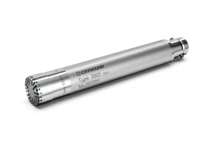
CRY3213 NVH Measurement Microphone
Field Type
Free-field
Sensitivity
50 mV/Pa, -26±2 dB re 1V/Pa
Frequency Response
3.15 Hz-20 kHz ±2 dB
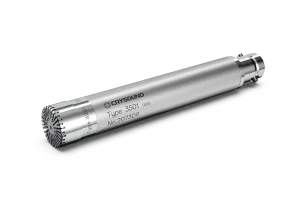
CRY3203-S01 Free-Field Microphone Set, 1/2", 50mV/Pa
Field Type
Free-field
Sensitivity
50mV/Pa, -26±1.5dB re 1V/Pa
Frequency Response
3.15Hz to 20kHz±2dB
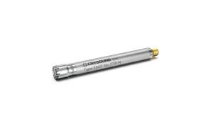
CRY3408-S01 Pressure-field Prepolarized High-level Microphone Set, 1/4", 0.14mV/Pa
Field Type
Pressure-field
Sensitivity
0.14 mV/Pa, -77±3 dB re 1V/Pa
Frequency Response
10 Hz to 20 kHz ±2 dB
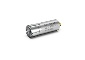
CRY3201-S01 Free-Field Microphone Set, 1/2", 12.5mV/Pa
Field Type
Free-field
Sensitivity
12.5mV/Pa, -38±1.5dB re 1V/Pa
Frequency Response
3.15Hz to 40kHz±2dB
CRY3202-S02 Pressure-Field Microphone Set, 1/2", 12.5mV/Pa
Field Type
Pressure-field
Sensitivity
12.5mV/Pa, -38±1.5dB re 1V/Pa
Frequency Response
3.15Hz to 20kHz±2dB
CRY3204-S01 Pressure-Field Microphone Set, 1/2", 50mV/Pa
Field Type
Pressure-field
Sensitivity
50mV/Pa, -26±1.5dB re 1V/Pa
Frequency Response
3.15Hz to 10kHz±2dB