CRYSOUND POCKET Acoustic Imaging Camera Now Available on Kickstarter.
CRYSOUND POCKET Acoustic Imaging Camera Now Available on Kickstarter.

Valves are the "core control components" of pipeline systems. They perform four key functions-opening/closing, regulating, isolating, and directing-enabling precise control of fluid flow. Once sealing integrity fails, minor cases can lead to process upsets and energy losses, while severe cases may result in fires or explosions, toxic exposure, or environmental pollution.
We built a valve leak application around the three things customers care about most on site-fewer missed detections and false alarms, better localization, and more reliable leak-rate estimation-by distilling them into an executable, traceable standardized workflow and closing the loop in the application for end-to-end deployment.
Common Causes of Valve Internal Leakage
What leads to valve leakage? We summarize it into the following four main causes:
- Normal wear and tear: Frequent opening and closing gradually wears the sealing surfaces; long-term scouring and erosion from the flowing medium can also degrade the seal fit.
- Process medium factors: Sulfur compounds and similar components in the medium can cause electrochemical corrosion; residual construction contaminants-such as sand, grit, and particles-can accelerate wear and scratch the sealing surfaces, leading to poor sealing.
- Improper operation and maintenance: Using an on/off valve for throttling, lack of routine cleaning and preventive maintenance, inadequate servicing, or improper/unsafe operation can all damage sealing surfaces or prevent full closure.
- Installation and management issues: Outdoor storage exposed to rain, ingress of mud and sand, and sandblasting/field conditions introducing grit or debris into the valve cavity can contaminate and scratch sealing surfaces, ultimately causing internal leakage.
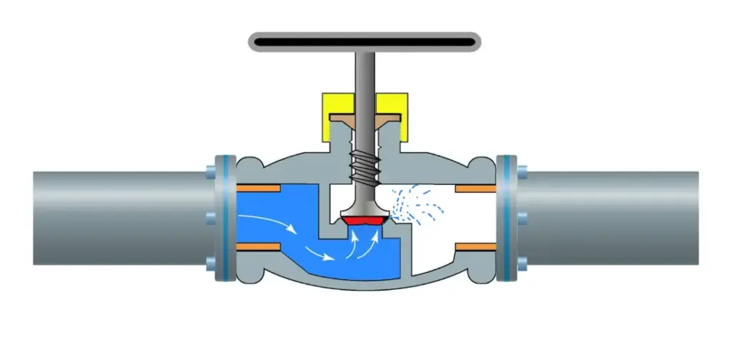
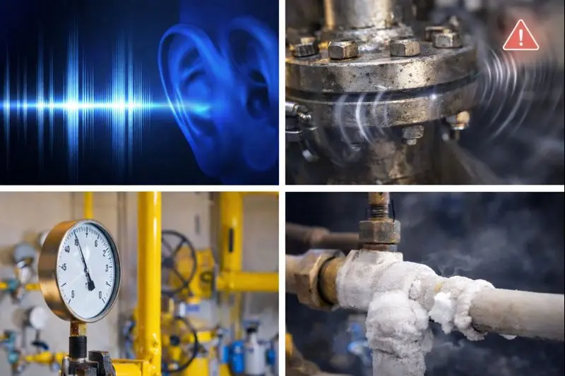
When a valve is closed but the sealing surfaces do not fully mate, the pressure differential drives the medium to pass through small gaps from the high-pressure side to the low-pressure side, forming high-velocity micro-jets and turbulent flow. This leakage typically results in several observable signs, including sound/ultrasound, vibration, abnormal pressure behavior, and temperature anomalies or frosting.
Why Contact Ultrasound Works
When a valve seal fails, high-pressure fluid passing through tiny gaps at the sealing surfaces generates turbulent flow, producing high-frequency ultrasonic signals in the 20-100 kHz range. The signal intensity is generally positively correlated with the leak rate-the larger the leak, the higher the amplitude.
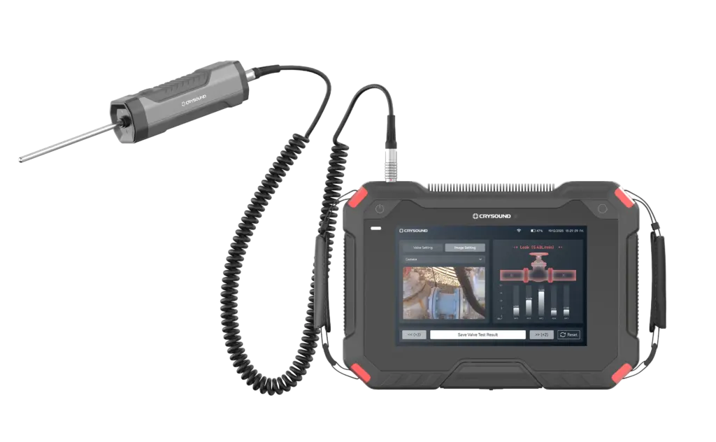
In the field, you can capture ultrasonic signals at measurement points upstream of the valve, on the valve body, and downstream, then apply algorithms to extract and analyze signal features to detect and localize internal leakage.
Compared with traditional methods, temperature-based approaches are easily affected by heat conduction and are difficult to quantify; pressure-hold tests are time-consuming and poor at pinpointing the leak location; and listening by ear is inefficient, prone to missed detections and false alarms, and heavily dependent on individual experience. That's exactly why we launched this application-turning an experience-driven task into a standardized, process-driven workflow, supported by acoustics and data analytics.
Workflow and Key Capabilities
More standardized workflow: turning on-site operation into guided testing
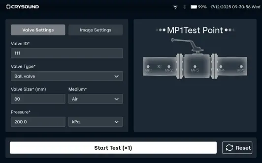
In the CRY8124 valve leak application, the software features a standardized and visualized workflow. Operators follow on-screen prompts to place the contact ultrasound sensor on each measurement point in sequence and simply tap "Test". The results are displayed on the interface, and the algorithm automatically determines whether internal leakage is present after the test.
At the same time, the software provides standardized inputs for key parameters such as valve ID, valve type, valve size, medium type, and the upstream/downstream pressure differential. This means test results are easier to align across the same unit, different shifts, and different operators-making retesting and trend management much more consistent.
Smarter: automatic diagnosis + leak-rate estimation
Our valve leak detection capability focuses on two key improvements:
- By analyzing the dB level at each measurement point and the features of the ultrasonic signal, the system automatically determines the internal leakage result based on algorithmic data, reducing reliance on manual interpretation.
- Built-in AI algorithms estimate the leak rate from ultrasonic features at the measurement points, providing a quantitative reference to support valve maintenance decisions.
This is the core logic behind our emphasis on a "higher detection rate": when judgments rely less on subjective experience, missed detections and false alarms become far more controllable-especially in complex sites with many valves and multiple parallel branches.
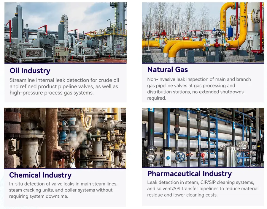
Application Scenarios
Across different industries, there is a common need for valve leak detection:
Field Case Study
Case : A Coal-to-Chemicals Plant in Inner Mongolia (Fuel Gas / Coal Gas System)
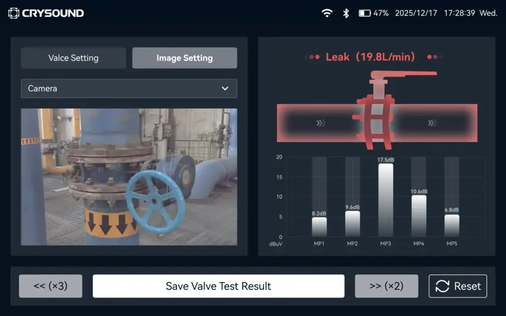
Below is a real field test case of valve leak at a coal-chemical plant. Any internal leakage in fuel gas or coal gas systems can compromise isolation. If leakage exists, the downstream side may remain gas-charged, and the work area may still be exposed to risks of CO and sulfur-containing acid gases entering the zone-potentially leading to poisoning, fire, or even explosion hazards. Using contact ultrasonics, we performed on-site testing on the suspected valves, quickly identified the leakage points, and estimated the leak rate. This helped the customer turn "isolation confirmed" from an experience-based judgment into data-backed verification, prioritize corrective actions, reduce work risks caused by misjudged isolation, and ensure safer maintenance and stable operation.

- Valve type: Fuel gas compressor room bypass valve (butterfly valve).
- Test result: 19.8 L/min.
- Medium / pressure: Fuel gas (H₂, CO, CH₄), 3 MPa.
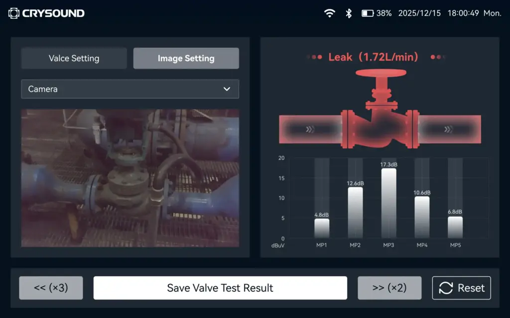
- Valve type: Fuel gas compressor room plug valve
- Test result: 1.7 L/min.
- Medium / pressure: Coal gas (mainly CO), 2.5 MPa.
On-Site Test Method: Repeatable 5-Point Measurements
Confirm Operating Conditions
Ensure there is a pressure differential, and isolate interfering branches as much as possible.
Key steps
- Close the valve to be tested.
- Open the upstream and downstream valves of the test section.
- Confirm a pressure differential between upstream and downstream gauges, and verify ΔP > 0.1 MPa.
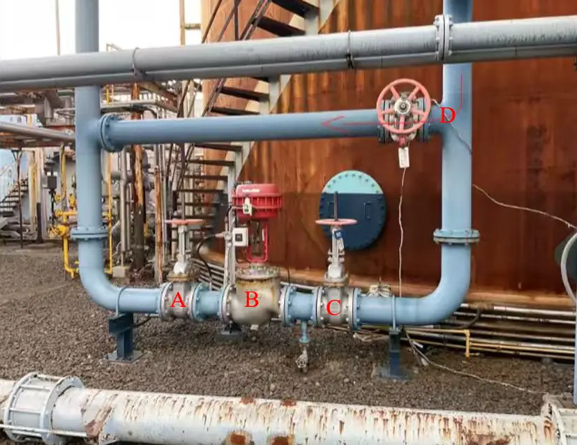
As shown in the figure below
- When testing Valve A for valve leakage: open Valves B and C, and close Valves A and D.
- When testing Valve B for valve leakage: open Valves A and C, and close Valves B and D.
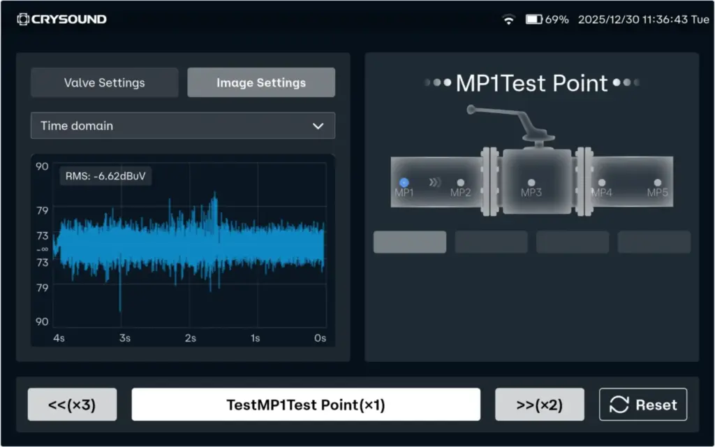
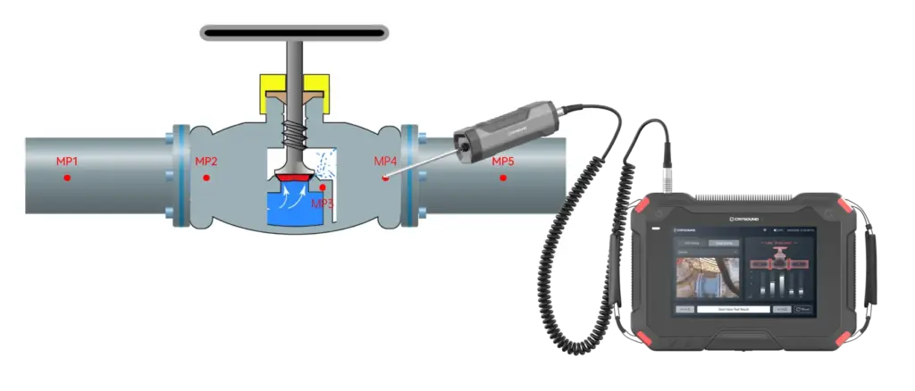
Place Measurement Points (MP1-MP5)
Cover upstream → valve core → downstream.
- MP3: Located at the valve core.
- MP2: Located 1-2 pipe diameters (D) upstream of the valve (place the point on the pipe wall away from the valve).
- MP1: Located upstream of the valve, 2-3D away from MP2. If space is limited, MP1-MP2 spacing can be shortened to 0.5D.
- MP4: Located 1D downstream of the valve (place the point on the pipe wall away from the valve).
- MP5: Located downstream of the valve, 1-2D away from MP4 (recommended on the pipe wall just after the valve flange). If space is limited, MP5-MP4 spacing can be shortened to 0.5D.
D = pipe diameter
Note
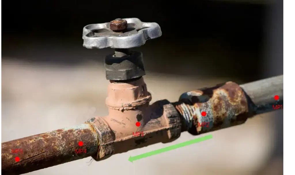
For small, flangeless threaded valves, the spacing between measurement points should be at least three pipe diameters (3D).
FAQ
We've listed some common scenario-based questions about valve internal leakage to help you understand the application faster and choose the right solution more efficiently.
Q1. How do I choose a Contact Ultrasound Sensor for pipelines at different temperatures?
A1. We recommend the following sensor selection based on pipe surface temperature:
- For low-temperature pipes (below -20°C) or high-temperature pipes (above 50°C), use a needle-type Contact Ultrasound Sensor.
- For temperatures between -20°C and 50°C, use a ceramic Contact Ultrasound Sensor for signal capture.
Q2. Which valves can be tested for valve leakage?
A2. This method is suitable for valve leakage detection across a wide range of valve types, including:
- Gate valves
- Plug valves
- Globe valves
- Ball valves
- Check valves
- Butterfly valves
- Needle valves
- Pressure relief valves
- Pinch valves
If your valve type is not listed above, please feel free to contact us.
Q3. Can we still test if the valve and pipe are insulated?
A3. If the insulation fully covers the valve and pipeline, testing may not be possible. You'll need to remove the insulation at the measurement area, or leave an opening of about 7 cm in diameter so the Contact Ultrasound Sensor can directly contact the pipe wall to capture the signal.
Q4. What should we pay attention to regarding the pipe surface during data collection?
A4. The Contact Ultrasound Sensor must make good contact with a solid surface to reliably capture ultrasonic signals propagating through the pipe. Large particles or debris between the sensor and the pipe surface can lead to inaccurate results. If the pipe wall is rusty, wipe off any large dust or loose particles on the surface before testing.
Contact Us
If you'd like to learn more about how CRYSOUND acoustics can be applied to valve leak detection, or if you want a more suitable inspection solution based on your on-site process conditions and acceptance criteria, please contact us via the form below. Our engineers will get in touch with you.
NEW
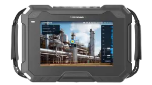
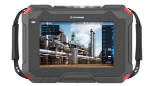
CRY8124 Advanced Acoustic Imaging Camera
Microphone array
200 channels MEMS microphone
Frequency range
2k - 100k Hz
SPL range
28 - 132 dB
NEW
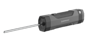
IA3104 Contact Ultrasound Sensor
Peak Sensitivity
>75 dB ISO 12714: 1999
Noise Floor
<10 μVRMS(15 - 70 kHz)
Size
35 × 40 × 135 mm, not including waveguide
NEW
CRY8125 Advanced Ex Acoustic Imaging Camera
Microphone Array
200 MEMS microphones
Frequency Range
2k - 100k Hz
SPL Range
28 - 132 dB


