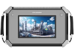
In this article, we use a wind turbine blade factory as an example to show how CRY8124 Acoustic Imaging Camera can help complete a vacuum (negative-pressure) integrity test for a single blade in about 10 minutes.

What Is a Wind Turbine Blade?
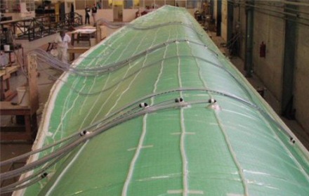
Wind turbine blades are the key rotor components that convert wind energy into mechanical power, which is then turned into electricity by the generator. They are typically made of glass-fiber or carbon-fiber composite materials and offer a high strength-to-weight ratio and strong corrosion resistance. The wind turbines you see on mountain ridges, in deserts, or along coastlines rely on these large blades to capture energy efficiently.
Why Vacuum Bag Integrity Testing Matters in Vacuum Infusion
In wind turbine blade manufacturing, vacuum bag airtightness during the vacuum infusion process is critical for stable vacuum levels and consistent laminate quality. Even small leaks can lead to process instability, additional troubleshooting time, and rework risk.
A typical workflow looks like this:
1. Preparation: Lay auxiliary materials (release fabric, flow media), seal the blade with vacuum film, block openings with sealing tape, and connect the vacuum pump, lines, and a gauge.
2. Evacuate to target vacuum: Start the pump and ramp to the process-defined vacuum level. If the target cannot be reached or keeps drifting, check high-risk areas first (especially sealant joints).
3. Vacuum hold & leak check: After reaching the specified vacuum level, turn off the pump and begin the hold phase (typically 10–30 minutes). Confirm the vacuum loss stays within your acceptance limit. If there is a leak, the vacuum level will drop noticeably—locate the leak point and repair it promptly.
4. Repair, re-test, document: Mark the leak points, replace any damaged vacuum film, and reseal the leaking areas. After repair, repeat evacuation and the vacuum hold test until the system meets the acceptance criteria, then document the results before proceeding to the next step.
Common Challenges in Wind Turbine Blade Vacuum Bag Testing
- A single blade can be 60–100 m long, creating a large sealing perimeter—so leak hunting can push the test beyond 30 minutes.
- Dense laminate around the blade root makes leaks harder to locate with traditional methods.
- Manual checks are slow and operator-dependent, leading to inconsistent results across shifts.
Case Study: Faster Leak Localization and Lower Rework Cost
At one blade manufacturer, routine vacuum-hold tests after bagging sometimes failed the hold criteria, leading to repeated troubleshooting and rework. The team introduced the CRY8124 Acoustic Imaging Camera as an assistive tool to locate leaks faster during pre-infusion checks.
Recommended Settings (Example)
- Turn on the CRY8124 and select the vacuum/leak scenario.
- Set the acoustic imaging band to 20–40 kHz.
- Adjust the imaging threshold (-40 dB to 120 dB) based on on-site conditions to reduce background noise from fans, cutting machines, and vacuum pumps.
- If ambient noise is high, enable focus/beamforming mode to further suppress environmental noise.
On-Site Leak Scanning Workflow
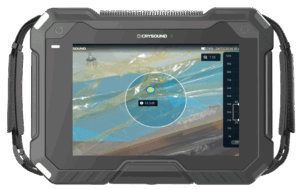
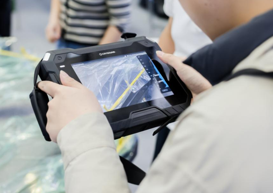
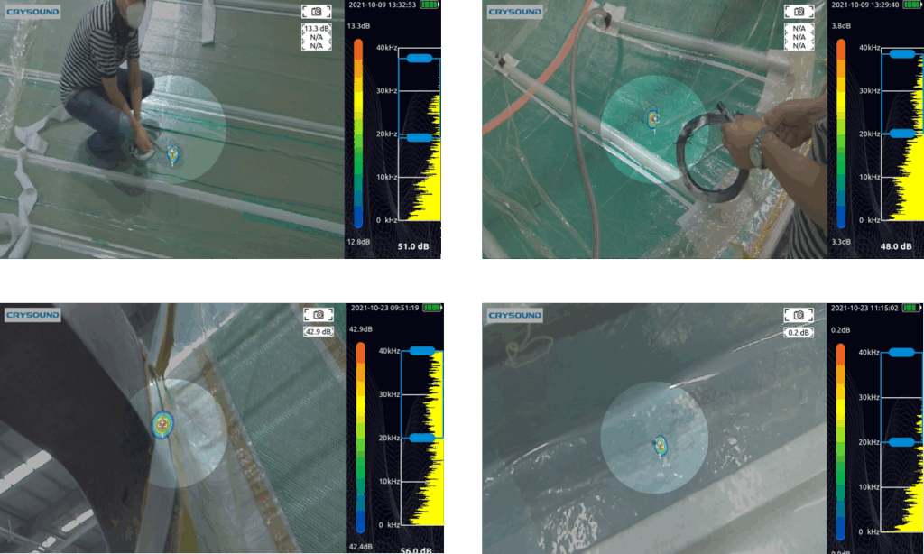
During inspection, the operator walks along key areas—such as the pressure side (PS), suction side (SS), the main-spar region, and around the root preform—while holding the CRY8124 Acoustic Imaging Camera. When a leak is present, the device overlays an acoustic “cloud map” on the live video feed, helping pinpoint the leak location and reducing repeated manual checks.
Measured Impact (Customer-Reported)
After introducing the CRY8124 Acoustic Imaging Camera, the average vacuum bag check time per blade dropped from 30+ minutes to around 10 minutes (about a 70% reduction in check time). The customer also reported annual cost savings exceeding $10,000 by reducing rework and scrap.
How a 10-Minute Vacuum Bag Check Is Achieved
The CRY8124 Acoustic Imaging Camera is designed for fast scanning across common blade inspection zones (PS/SS surfaces, main spar region, and the blade root). It provides a visual indication of leak location and relative leak severity, while using frequency filtering and beamforming to work in noisy production environments. With a high-density microphone array (up to 200 microphones, depending on configuration) covering 2 kHz–100 kHz, the system can capture ultrasonic components from small leaks and render them as an intuitive acoustic image.
If you’d like to learn more about acoustic imaging for vacuum leak detection—or discuss your blade process and inspection targets—please use the “Get in touch” form below. Our team can share recommended settings and an on-site workflow tailored to your production conditions.
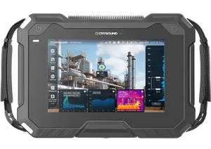
CRY8124 Advanced Acoustic Imaging Camera