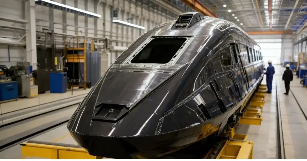
Negative-pressure airtightness is critical for high-speed train car bodies, and even minor leaks can lead to rework or delivery risks. This article presents a case from Changchun where CRYSOUND's CRY8124 Acoustic Imaging Camera was used to quickly, intuitively, and verifiably pinpoint leaks on a carbon-fiber train car body shell, showcasing the CRY8124's application in vacuum leak detection for carbon-fiber high-speed train car bodies.
Case Snapshot
- Year: 2025
- Location: Changchun
- Workpiece: Carbon-fiber train car body shell
- Test condition: Vacuum/negative-pressure setting; 15-minute pressure-hold test
- Sample size: 4 units
- Coverage: Scanned 6 key areas (car-body section joints/seams, structural interfaces, process holes, corners/curved transition areas, edge of cover film, around embedded components, etc.)
- Participants: CRYSOUND's Technical Engineers
- Deliverables: Acoustic imaging heatmap images/videos + report
Project Background: Vacuum Leaks Are "Hard to Find, Time-Consuming, and Easy to Miss"
Carbon-fiber car body shells feature complex structures with numerous joints and interfaces. When a leak exists during negative-pressure testing, traditional methods often face three common challenges:
- Experience-dependent localization: Requires repeated "listen-feel-try" steps, and heavily depends on operator skill and experience.
- High interference: Background noise from workshop fans, tools, friction, and impacts can mask weak leak signals.
- Inconsistent efficiency: Troubleshooting time varies significantly between operators for the same issue, making verification difficult.
On-Site Approach: Pinpointing Leaks with "Visible Sound"
In this project, CRY8124 Acoustic Imaging Camera was used to perform scan-based inspections across key areas of the shell. The core value of acoustic imaging lies in making the sound source generated by a leak visible on the screen-turning leak localization from "guessing" into "seeing."
On-Site Inspection Procedure:
- Maintain the negative-pressure condition: Troubleshooting was performed under the customer's specified negative-pressure (vacuum gauge pressure approx. -100 kPa) test state.
- Selected frequency range: Based on on-site verification, 20-40 kHz was selected (offset from the dominant background-noise frequencies, providing better contrast for leak sources).
- Selected imaging threshold: Based on on-site verification, an imaging threshold of -40 dB was selected
- Scan and locate: Move the device along high-risk areas such as seams, interfaces, corners, and the edges of cover films.
- Point verification: Re-test suspected sound-source points at close range and mark them; adjust angles as needed for confirmation (strong airflow, film vibration, or strong reflections may create false leak indications, so multi-angle rechecks are required).
- Evidence output: Save images/videos with acoustic heatmap overlays to support on-site closure and quality documentation. Reports can later be generated using CRYSOUND's second-generation analysis software.
Inspection Results: Multiple Leaks Quickly Identified
Under the customer's specified negative-pressure test conditions at a train manufacturing site in Changchun, acoustic imaging scan inspections were carried out on a carbon-fiber train car body shell.
- Multiple vacuum leak points identified: A total of three suspected leak points were marked. Rechecks were performed using a temporary sealing (blocking) comparison method. After the leak points were sealed, there was no measurable pressure drop, confirming three leak points. All confirmed points were marked on-site, and images/videos with the leak heatmap overlays were saved for quality documentation and verification.
- Efficiency: On average, the total inspection time per component-from "start scanning" to "finish inspection, marking, and saving evidence / completing verification"-was under 10 minutes.
- Closed-loop validation: After corrective actions, a re-inspection was performed under the same conditions. The leak heatmap disappeared, and the workpiece passed the customer's pressure-hold specification.
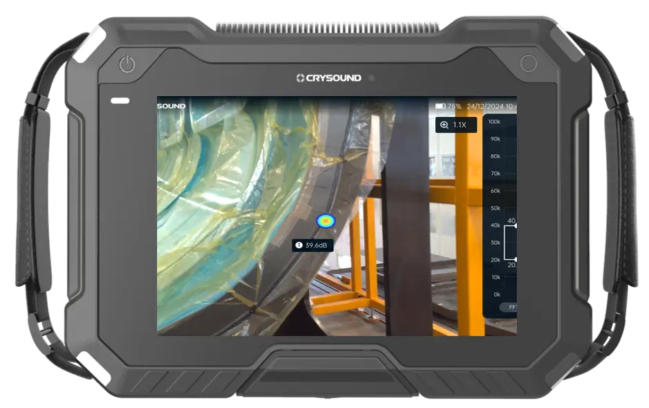
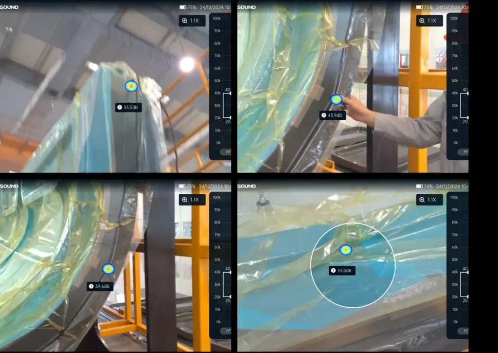
From the on-site inspection visuals, different leak points consistently appeared as stable acoustic heatmap overlays on the device interface.
Why Is Acoustic Imaging Well Suited for This Process?
From the perspective of airtightness testing for composite structures, vacuum leak detection is not short of methods that can "find a problem." The real challenge is achieving results that are fast, accurate, visual, and verifiable. In composite car-body applications, the advantages of acoustic imaging mainly include:
- Visual localization: Leak points are overlaid directly onto the surface of the structure as acoustic heatmaps, making the leak location visible and reducing communication and handoff costs.
- Stronger resistance to environmental interference: By selecting an appropriate frequency range and setting the imaging threshold, the contrast between leak sources and background noise is improved, minimizing the impact of ambient interference on results.
- More controllable efficiency: As a handheld tool, the cycle time is more consistent, making it suitable for batch inspections and production-line management.
- Traceable evidence: Images and videos can be retained for review, quality traceability, and training purposes.
Practical Tips: How to Be "Faster and More Accurate" On Site
Based on our on-site experience in Changchun, here are three actionable recommendations:
- Prioritize high-risk geometries: seams, hole edges, corners, cover-film edges, and interface transition areas.
- Image first, then verify up close: use the device to identify suspected leak points first, then confirm them at close range and from multiple angles.
- Standardize the documentation template: save images/videos for every point to support corrective actions, test report writing, and follow-up verification.
Conclusion: Turning Troubleshooting from "Experience-Based Work" into a Standardized Process"
In vacuum leak detection for carbon-fiber train car body shells, CRY8124 Acoustic Imaging Camera upgrades "listening for leaks" into visualized localization, delivering a closed-loop outcome with higher efficiency, clearer pinpointing, and retained evidence-while significantly reducing reliance on individual experience.
If you'd like to learn more about the application of CRY8124 Acoustic Imaging Camera for vacuum leak testing, or discuss a detection solution better suited to your composite-material process and acceptance criteria, please contact us via the form below. Our sales or technical support engineer will get in touch with you.