In acoustic testing, sensor calibration, electroacoustics, and NVH, gain, input range, and quantization directly determine the quality of the data you capture. This article explains these three factors from an engineering perspective. Using typical CRYSOUND setups—measurement microphones, preamps, acoustic imaging systems, and DAQ system such as SonoDAQ Pro with OpenTest—it shows how to configure them correctly in practice.
From the Test Floor: When “Weird Waveforms” Are Caused by Quantization
In real acoustic test environments, engineers often encounter situations like these:
- On a production line, waveforms from a batch of MEMS microphones suddenly look stair-stepped, and the spectrum becomes rough.
- In NVH or fan noise tests, low-level waveform sections appear grainy, with details barely visible.
- In acoustic imaging systems, signals from distant leakage points are audible but unstable, with jittery image edges.
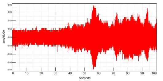
Figure 1: Data with poor quantization quality often appears noisy or blurred.
Many engineers initially attribute these issues to excessive noise. In practice, a large portion of them result from signals that are too small relative to an overly large input range, causing most quantization levels to be wasted.
If a signal does not sufficiently occupy the system’s dynamic range, even a high-resolution ADC cannot deliver meaningful data quality.
Three Core Concepts Explained in Engineering Terms
Gain: Bringing the Signal into the Right Zone
In CRYSOUND acoustic measurement chains, gain is typically applied in the following parts:
- Measurement microphone and preamplifier stages
- Electroacoustic analyzers or DAQ front ends such as SonoDAQ Pro
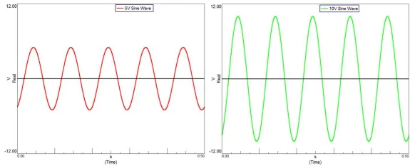
Figure 2: Left: a 5 V signal. Right: applying a gain of 2 to the 5 V signal, resulting in a 10 V signal.
The purpose of gain is straightforward: amplify signals that may only be tens or hundreds of millivolts so they approach the DAQ’s full-scale input and can be properly digitized by the ADC.
Range: The Window Through Which the System Sees the Signal
Input range defines both the maximum signal amplitude a system can accept and the voltage step corresponding to each quantization bit at a given ADC resolution.
For high-precision devices such as CRYSOUND measurement microphones and sound level meters like CRY2851, selecting an appropriate range that keeps the signal within the linear operating region is essential for stable measurements.
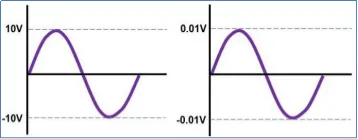
Figure 3: Left: input range set to 10 V. Right: input range set to 0.01 V.
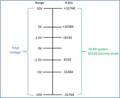
Figure 4: Number of available bins used for signal quantization.
Quantization: Translating the Analog World into Digital Data
Quantization is the process by which an ADC converts continuous analog signals into discrete digital values. When more quantization levels are effectively used, the digital signal represents the analog waveform more faithfully. When fewer levels are used, stair-step waveforms and low-level jitter become apparent.
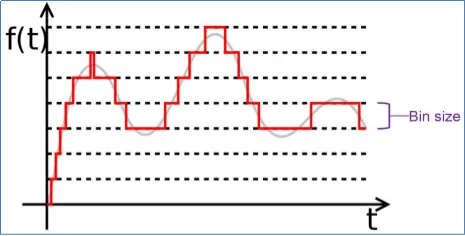
Figure 5: During quantization, the signal amplitude is divided into discrete levels.
How Gain and Range Work Together in CRYSOUND Systems
The interaction between gain, range, and quantization becomes clearer when viewed through real CRYSOUND application scenarios.
1. Sensors and Electroacoustic Testing
CRYSOUND measurement microphones, preamplifiers, and electroacoustic analyzers (e.g., CRY6151B) are commonly used for:
- Microphone capsule testing;
- Production-line and laboratory testing of headphones, loudspeakers, and other electroacoustic components.
In these systems, the typical best practice is:
- Estimate the signal level based on the DUT sensitivity and the expected sound pressure level (SPL);
- Set an appropriate gain on the front-end amplifier or analyzer so the signal reaches about 60–80% of full scale;
- Select a matching input range to avoid clipping while also preserving as much dynamic range as possible.
This approach delivers low distortion while making full use of the ADC’s effective bits, reducing quantization noise.
2. Acoustic Imaging and Array Measurements
In CRYSOUND acoustic imaging products (e.g., acoustic imaging cameras based on high-performance microphone arrays), the system often processes wideband signals from many synchronized channels, then applies localization and imaging algorithms.
In this scenario:
- If the signal level from a given direction is far below the lower limit of the overall range, that area may suffer from insufficient quantization resolution, resulting in more image speckle/noise;
- Properly setting the overall array gain and the input range of each front-end module helps balance weak far-field signals against strong near-field signals.
That’s why, for gas leak detection, partial discharge identification, or mechanical degradation monitoring, a reliable acoustic imaging system depends not only on algorithms, but also on the underlying quantization quality.
3. DAQ Systems and Repeatable Workflows
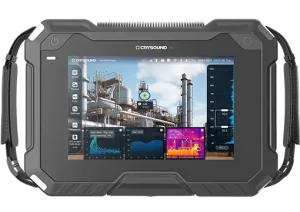
For acoustic and vibration acquisition, CRYSOUND provides modular DAQ hardware (e.g., the SonoDAQ series) and the OpenTest software platform, enabling end-to-end workflows from measurement and analysis to automated test sequences.
On these platforms, engineers can:
- Configure per-channel sensor gain, range, and sampling rate directly in the channel settings;
- Save a validated configuration as a template and reuse it across different products or projects;
- Use wizard-style interfaces in applications such as sound power, noise, and vibration to ensure parameter settings remain aligned with relevant standards.
In other words:
Gain, range, and quantization—these “low-level details”—can be captured in software scenario templates and turned into shared, auditable testing assets for the team, instead of living only in one engineer’s experience.
A Quick Cheat Sheet for CRYSOUND Users
Whether you are using CRYSOUND measurement microphones, sound level meters, electroacoustic test systems, or a DAQ + OpenTest platform, the checklist below can be used as a quick pre-test verification in daily work.
- Confirm the expected signal range: Estimate the maximum signal amplitude using experience or a short trial capture.
- Set an appropriate front-end gain: Target is under typical operating conditions, waveform peaks should reach about 60–80% of full-scale input.
- Select a matching input range: Avoid defaulting to ±10 V; if the signal level is clearly lower, consider using a smaller range.
- Check for clipping: Flat-topped waveforms or abnormally elevated spectral lines usually indicate overload.
- Save and reuse configurations: In CRYSOUND platforms, save channel, gain, and range settings as project templates to reduce human error.
Closing: Accuracy Comes from the Entire System
In real acoustic measurement systems, data quality is never determined by a single ADC alone. Instead, it is the result of the entire signal chain working together:
Sensors → Amplification → Range → Quantization → Software Algorithms
As an acoustic testing specialist, CRYSOUND aims to help engineers address these fundamental issues—gain, range, and quantization—through a complete product portfolio, from sensors and front-end hardware to acoustic imaging, electroacoustic testing, data acquisition, and software platforms. This provides a reliable data foundation for subsequent analysis and decision-making.
If you’d like help choosing the right setup or validating your configuration, please fill out the Get in touch form and we’ll contact you.
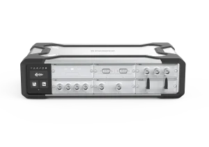
SonoDAQ Pro

OpenTest