In acoustic measurements (SPL, frequency response, noise, reverberation, etc.), large errors often come not from instrument accuracy, but from a mismatch between the assumed sound field and the actual one. What a microphone reads as sound pressure is not strictly equivalent across different fields—especially at mid and high frequencies, where the microphone dimensions become comparable to the acoustic wavelength.
Measurement microphones are commonly categorized by the field for which their calibration/compensation is defined: Free-field, Pressure-field, and Diffuse-field (Random incidence). This article uses engineering-oriented comparison tables and common-pitfall checklists to explain the differences among the three sound-field types, their typical application scenarios, and key usage considerations. It also provides selection rules that can be directly incorporated into test plans, helping to improve measurement repeatability and comparability.
Build Intuition With One Picture
The following diagrams illustrate the three typical sound-field assumptions used in microphone calibration and selection.
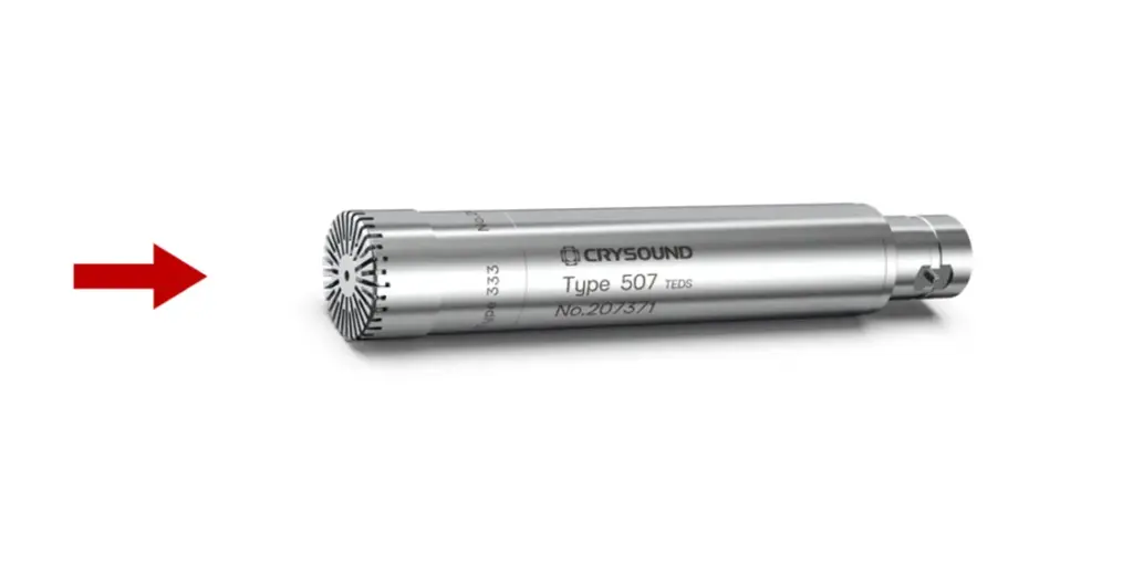
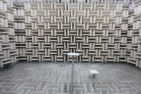
Figure 1 Free field: reflections negligible, wave incident mainly from one direction
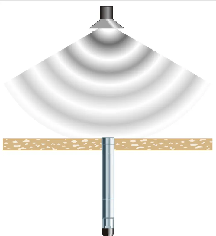
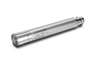
Figure 2 Pressure field: coupler/cavity measurement focusing on diaphragm surface pressure

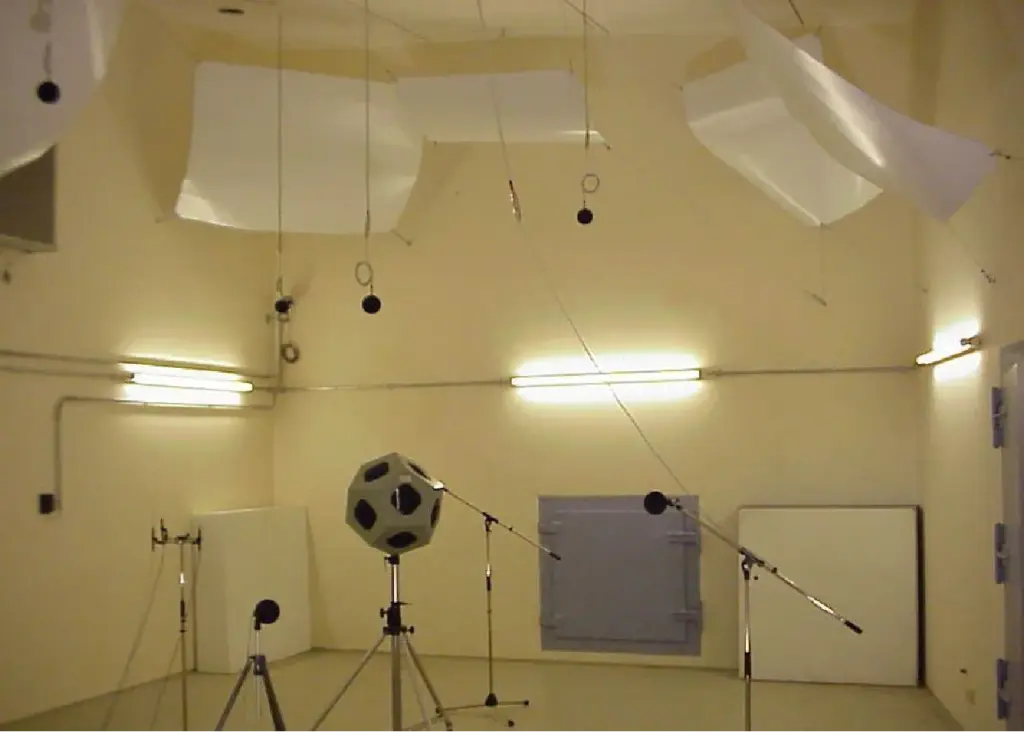
Figure 3 Diffuse (random-incidence) field: energy arrives from many directions (statistical sense)
Quick Comparison for Engineering Selection
| Type | Field assumption | Typical scenarios | Placement / orientation | Main error drivers |
| Free-field microphone | Reflections negligible; primarily single-direction incidence (often 0°) | Anechoic measurements; on-axis loudspeaker response; front-field SPL | Aim at source (0°) | Angle deviation; unintended reflections; fixture scattering |
| Pressure-field microphone | Measure true pressure at diaphragm surface (often in small cavities) | Couplers; ear simulators; boundary/flush measurements | Flush-mounted or connected to coupler | Leaks; cavity resonances; coupling repeatability |
| Diffuse-field (random-incidence) microphone | Energy arrives from all directions with equal probability (statistical) | Reverberation rooms; highly reflective enclosures; diffuse-field tests | Orientation less critical, but mounting must be controlled | Not truly diffuse in real rooms; local blockage/reflections |
Free Field: Estimate the Undisturbed Sound Pressure
A free field is an environment where reflections are negligible and sound arrives mainly from a defined direction (commonly 0° to the microphone axis). Because the microphone body perturbs the field, a free-field microphone typically includes free-field compensation, so the indicated pressure better represents the pressure that would exist without the microphone in place.
Typical Use Cases
- Anechoic or quasi-free-field SPL measurements
- On-axis loudspeaker frequency response and source characterization
- Tests with a strictly defined incidence direction
Practical Notes
- Keep 0° incidence when specified; off-axis angles can cause significant high-frequency deviations.
- Minimize scattering from fixtures (stands, adaptors, fixture、cable、windscreens).
- Control nearby reflective surfaces that break the free-field assumption.
Pressure Field: Measure Diaphragm Surface Pressure
A pressure field is commonly associated with small enclosed volumes (couplers/cavities). Here, the quantity of interest is the true pressure at the diaphragm surface. The microphone often becomes part of the cavity boundary.
Typical Use Cases
- Pistonphone/coupler calibration and cavity measurements
- IEC ear simulators and couplers for headphone and in-ear testing
- Flush/boundary pressure measurements
Practical Notes
- Seal and coupling are critical; small leaks can strongly affect low and mid frequencies.
- Cavity resonances can shape high-frequency response; follow the applicable standard or method.
- Maintain consistent mounting force and assembly for repeatability.
Diffuse Field: An Average Over Angles
A diffuse field (random incidence) assumes that sound energy arrives from all directions with equal probability, in a statistical sense. This is approached in reverberation rooms or highly reflective enclosures. Diffuse-field microphones are designed so their response better matches the average over many incidence angles.
Typical Use Cases
- Reverberation-room measurements and room acoustics
- Noise and SPL measurements in reflective cabins (vehicle or enclosure)
- Statistical measurements where multi-direction incidence dominates
Practical Notes
- A normal room is not necessarily diffuse; strong direct sound breaks the assumption.
- Proper installation and operation remain essential: large fixtures, mounting brackets, and obstructions can alter the characteristics of the local acoustic field.
- Keep measurement locations consistent; position changes alter modal and reverberant contributions.
Rule of Thumb: Write the Field Assumption into the Test Plan
- Quasi-anechoic, direction defined → choose a free-field microphone
- Coupler/cavity/boundary pressure → choose a pressure-field microphone
- Highly reflective, multi-direction incidence → choose a diffuse-field microphone
When the field is uncertain, define the geometry first (direct-to-reverberant ratio, incidence direction, distance), then apply an appropriate calibration or correction strategy to control the dominant error sources.
Common Pitfalls
- Using a free-field microphone in a coupler/cavity: high-frequency deviations are often exaggerated.
- Free-field testing without controlling angle: off-axis error grows at mid and high frequencies.
- Treating a normal room as diffuse: if direct sound dominates, the diffuse-field assumption fails.
Conclusion
Free field, pressure field, and diffuse field are not marketing terms—they tie microphone design and calibration assumptions to specific acoustic models. By explicitly documenting the assumed field (geometry, angle, reflections, calibration and corrections) in your test plan, you can significantly improve repeatability and comparability across measurements.
To learn more about microphone functions and measurement hardware solutions, visit our website—and if you’d like to talk to the CRYSOUND team, please fill out the “Get in touch” form.
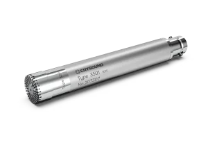
CRY3204-S01 Pressure-Field Microphone Set, 1/2", 50mV/Pa