During pilot production and production line ramp-up, many issues do not appear in the way teams initially expect. Sometimes it starts with a small fluctuation at a test station, or a comment from a line engineer saying, "This result looks a bit unusual."
However, when takt time, yield targets, and delivery milestones are all under pressure, these seemingly minor anomalies can quickly be amplified and begin to affect the overall production rhythm.
We have been working with Huaqin as a long-term partner. As projects progressed, the challenges encountered on the production line became increasingly complex. On site, our role gradually extended from basic production test support to problem analysis and cross-team coordination during pilot production. In many cases, the focus was not simply on whether a test station was functioning, but on how to absorb uncertainties early and prevent them from disrupting delivery schedules.
The following two experiences both took place during the pilot production phase of Huaqin projects. They are not exceptional cases. On the contrary, they represent the kind of everyday issues that most accurately reflect the realities of production line delivery.
Airtightness Testing Issues in Project α
During the pilot ramp-up of Project α, the airtightness test station for the audio microphone showed clear instability. For the same batch of products, pass rates fluctuated noticeably across repeated tests, frequently interrupting the station's operating rhythm. Initial troubleshooting naturally focused on the test system itself, including software logic, equipment status, and basic parameter settings. It soon became clear, however, that the issue did not originate from these areas.
As on-site verification continued, we gradually confirmed that the anomaly was more closely related to the product's mechanical structure and material characteristics. This model used a relatively uncommon combination of materials. A sealing solution that had worked well in previous projects could not maintain consistency during actual compression. Even slight variations in applied pressure were enough to influence test results.
Once the direction of the problem was clarified, the on-site approach shifted accordingly. Rather than repeatedly adjusting the existing solution, we returned to verifying the compatibility between materials and structure. Over the following period, we worked together with the customer's engineering team on the production line, testing multiple material options. This included different types of silicone and cushioning materials, variations in silicone hardness, and adjustments to plug compression methods. Each step was evaluated based on real test results before moving forward.
The process was not fast, nor was it particularly clever. In essence, it came down to repeatedly confirming one question: could this solution run stably under real production line conditions?
Ultimately, by introducing a customized soft silicone gasket and making fine parameter adjustments, the airtightness test results gradually stabilized. The station was able to run continuously, and the pilot production rhythm was restored.
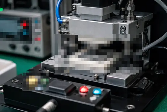
Figure 1. Test Fixture Diagram
Noise Floor Issues in Project β
Compared with the airtightness issue in Project α, the noise floor anomaly encountered during pilot production in Project β was more complex to diagnose.
During headphone pilot production for Project β at Huaqin's Nanchang site, the noise floor test station repeatedly triggered alarms. Test data showed that measured noise levels consistently exceeded specification limits, significantly impacting the pilot production schedule. This model used high-sensitivity drivers along with a new circuit design, making the potential noise sources inherently more complex. It was not a problem that could be resolved by simply adjusting a single parameter.
Rather than focusing solely on the test station, we worked with the customer's audio team to investigate the issue from a system-level signal chain perspective. The process involved sequentially testing different shielding cables, adjusting grounding strategies, evaluating various Bluetooth dongle connection methods, and isolating potential power supply and electromagnetic interference sources within the test environment.
Through continuous spectrum analysis and comparative testing, the scope of the issue was gradually narrowed. It was ultimately confirmed that the elevated noise floor was primarily related to power interference from the Bluetooth dongle, combined with differences in product behavior across operating states. After this conclusion was reached, relevant configurations were adjusted and validated on site. As a result, noise floor measurements returned to a stable and controllable range, allowing pilot production to proceed.
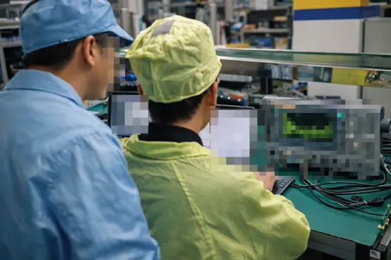
Figure 2. Work with the customer engineer to solve problems
Common Characteristics of Pilot Production Issues
Looking back at these two pilot production experiences, it becomes clear that despite their different manifestations, the underlying diagnostic processes were quite similar. Whether dealing with airtightness instability or excessive noise, the root cause could not be isolated to a single module. Effective resolution required on-site evaluation across mechanical structure, materials, system operating states, and test conditions.
During pilot production, issues of this nature rarely come with ready-made answers. They are also unlikely to be resolved through a single verification cycle. More often, progress is made through repeated trials, comparisons, and eliminations, gradually converging on a solution that is genuinely suitable for long-term production line operation.
Production line delivery rarely follows a perfectly smooth path. In many cases, what ultimately determines whether a project can move forward as planned are those unexpected issues that must be addressed immediately when they arise. In our long-term collaboration with customers, our work often takes place at these critical moments—working alongside engineering teams to stabilize processes, maintain momentum, and keep projects moving forward step by step. If you also want CRYSOUND to support your production line, you can fill out the Get in Touch form below.
Get Expert Advice for Your Application
Tell us about your testing requirements and our engineers will recommend the right solution.
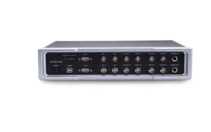
CRY6151B Electroacoustic Analyzer
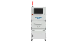
CRY725D Pneumatic Acoustic Test Chamber
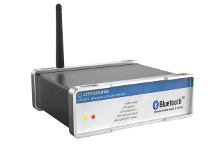
CRY578 Bluetooth LE Audio Interface
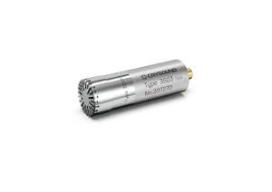
CRY3203-S02 Free-Field Microphone Set, 1/2", 50mV/Pa