CRYSOUND POCKET Acoustic Imaging Camera Now Available on Kickstarter.

In acoustic design and noise control, a material's acoustic impedance characteristics are a key factor in determining "how it sounds." By measuring parameters such as the absorption coefficient, reflection coefficient, specific acoustic impedance, and acoustic admittance, we can not only quantify a material's ability to absorb and reflect sound, but also evaluate its performance in real-world applications-such as room reverberation time, noise-control effectiveness in equipment, and the acoustic comfort of products like automobiles and home appliances. Accurate acoustic impedance testing gives engineers solid evidence for material selection, structural optimization, and acoustic simulation, dramatically reducing trial-and-error costs and shifting acoustic design from experience-driven to data-driven.
Advantages of the Transfer-Function Method
Among the many acoustic impedance measurement methods, the transfer-function method is widely used thanks to its fast testing speed, high accuracy, and broad applicable frequency range. By placing two microphones inside an impedance tube and using the sound-pressure transfer function, one can back-calculate parameters such as the absorption coefficient, reflection coefficient, and specific acoustic impedance-without complicated sound-source calibration or overly idealized assumptions about the sound field. Compared with the traditional standing-wave ratio method, the transfer-function method depends less on operator experience, delivers more stable low-frequency measurements, and is easier to automate and post-process, making it well suited for R&D, material screening, and high-throughput quality inspection in industry.
CRYSOUND Integrated Test Solution
CRYSOUND provides a complete acoustic impedance testing solution. Built around the CRY6151B data acquisition unit, and combined with our in-house algorithms plus testing software and an impedance-tube hardware system, it delivers an integrated workflow-from equipment calibration and data acquisition to parameter calculation and report generation.
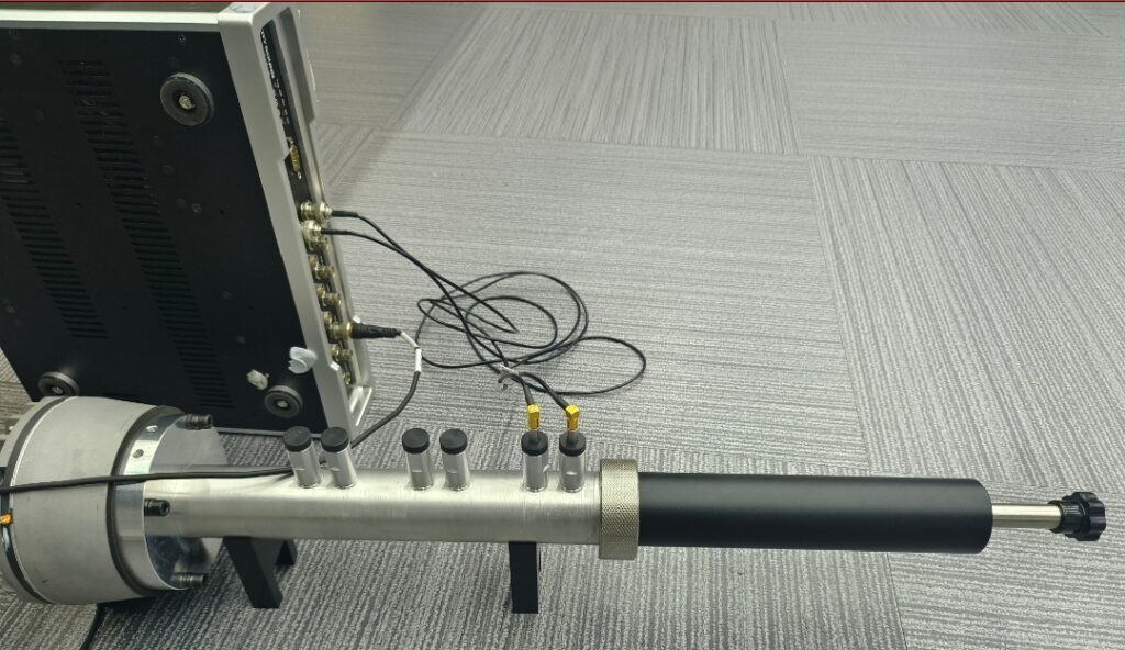
In terms of hardware configuration, we use a measurement chain optimized specifically for acoustic impedance testing. At the front end, two 1/4-inch pressure-field measurement microphones (CRY3402) are deployed. While ensuring a wide frequency range and wide dynamic range, they maintain excellent linearity and stability under high sound-pressure levels-making them ideal for precise measurements in the high-SPL sound field inside an impedance tube. At the back end, a CRY6151B data acquisition unit handles signal acquisition and output control, featuring low noise floor, stable output, and a clean, straightforward interface and operating logic.
On the software side, we provide a complete workflow covering calibration, measurement, analysis, and reporting-making the tedious yet critical steps in acoustic impedance testing both meticulous and easier for users. Before testing, the software guides users through input/output calibration to ensure the gain and phase of the excitation output and acquisition channels are under control. It then performs a signal-to-noise ratio (SNR) check, automatically evaluating whether the current test environment and hardware configuration meet the conditions for valid measurements, avoiding wasted time under low-SNR conditions.
To match the characteristics of the transfer-function method, the software integrates transfer-function calibration and dual-microphone acoustic-center distance calibration modules. Through dedicated calibration procedures, it automatically corrects inter-channel amplitude/phase errors and microphone acoustic-center position offsets, reducing high-frequency ripple and computational error at the source. It also supports flange-tube calibration, compensating for leakage and geometric deviations at flange connections so that reliable absorption-coefficient and acoustic-impedance results can still be obtained even under conditions close to real-world use. The entire workflow complies with the requirements of GB/T 18696.2-2002.
During actual measurements, the software supports multiple excitation types, including random noise and pseudo-random noise for rapid wideband scanning, as well as single-tone signals for precisely locating resonance frequencies and analyzing the relationship between impedance and sound speed - useful for material mechanism research or fine tuning. After the test, the data can be displayed in multiple band formats, and curves from different samples or operating conditions can be compared within the same interface. Users can view key parameter curves such as the absorption coefficient, reflection coefficient, and specific acoustic impedance, and can also automatically generate a test report that includes measurement conditions and result plots, greatly improving the efficiency and standardization of acoustic impedance testing.
Overall, acoustic impedance testing is both a "magnifying glass" for understanding a material's acoustic properties and a "ruler" for translating acoustic design into engineering reality. With an optimized hardware chain (CRY3402 microphones + CRY6151B data acquisition unit) and an integrated software platform that combines calibration, measurement, analysis, and reporting, we aim to make acoustic impedance testing-once a highly specialized and complex task-controllable, visual, and repeatable, truly supporting product R&D, quality control, and acoustic-experience improvement for enterprises.
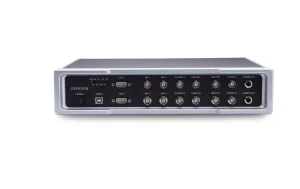
CRY6151B Electroacoustic Analyzer
Quantity of Channels
4-channel input/output (scalable for synchronous 8-channel input/4-channel output)
Sample Rate
All channels for simultaneous sampling at 44.1kHz - 192kHz, with 24-bit
Input Dynamic Range
115dB typical value
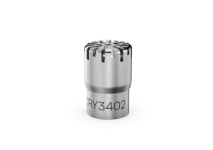
CRY3402 Pressure-field Microphone, 1/4" Prepolarized, 1.6mV/Pa
Field Type
Pressure-field
Noominal Sensitivity
1.6mV/Pa, -56±3dB re 1V/Pa
Frequency Response
4Hz to 70kHz±2dB


