

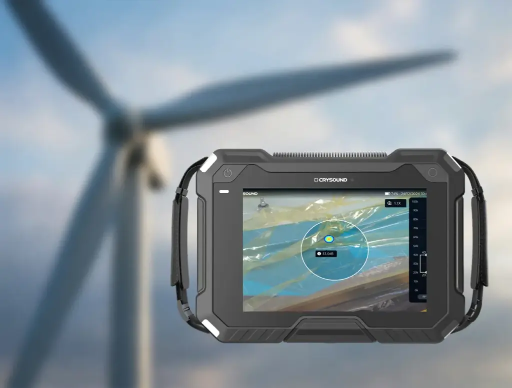
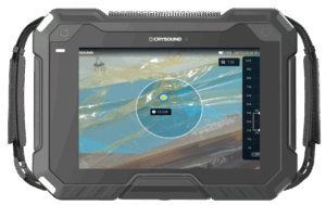
In this article, we use a wind turbine blade factory as an example to show how CRY8124 Acoustic Imaging Camera can help complete a vacuum (negative-pressure) integrity test for a single blade in about 10 minutes.

What Is a Wind Turbine Blade?
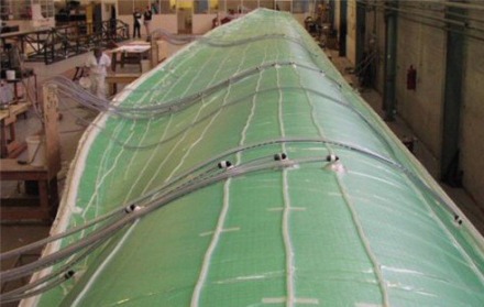
Wind turbine blades are the key rotor components that convert wind energy into mechanical power, which is then turned into electricity by the generator. They are typically made of glass-fiber or carbon-fiber composite materials and offer a high strength-to-weight ratio and strong corrosion resistance. The wind turbines you see on mountain ridges, in deserts, or along coastlines rely on these large blades to capture energy efficiently.
Why Vacuum Bag Integrity Testing Matters in Vacuum Infusion
In wind turbine blade manufacturing, vacuum bag airtightness during the vacuum infusion process is critical for stable vacuum levels and consistent laminate quality. Even small leaks can lead to process instability, additional troubleshooting time, and rework risk.
A typical workflow looks like this:
1. Preparation: Lay auxiliary materials (release fabric, flow media), seal the blade with vacuum film, block openings with sealing tape, and connect the vacuum pump, lines, and a gauge.
2. Evacuate to target vacuum: Start the pump and ramp to the process-defined vacuum level. If the target cannot be reached or keeps drifting, check high-risk areas first (especially sealant joints).
3. Vacuum hold & leak check: After reaching the specified vacuum level, turn off the pump and begin the hold phase (typically 10–30 minutes). Confirm the vacuum loss stays within your acceptance limit. If there is a leak, the vacuum level will drop noticeably—locate the leak point and repair it promptly.
4. Repair, re-test, document: Mark the leak points, replace any damaged vacuum film, and reseal the leaking areas. After repair, repeat evacuation and the vacuum hold test until the system meets the acceptance criteria, then document the results before proceeding to the next step.
Common Challenges in Wind Turbine Blade Vacuum Bag Testing
- A single blade can be 60–100 m long, creating a large sealing perimeter—so leak hunting can push the test beyond 30 minutes.
- Dense laminate around the blade root makes leaks harder to locate with traditional methods.
- Manual checks are slow and operator-dependent, leading to inconsistent results across shifts.
Case Study: Faster Leak Localization and Lower Rework Cost
At one blade manufacturer, routine vacuum-hold tests after bagging sometimes failed the hold criteria, leading to repeated troubleshooting and rework. The team introduced the CRY8124 Acoustic Imaging Camera as an assistive tool to locate leaks faster during pre-infusion checks.
Recommended Settings (Example)
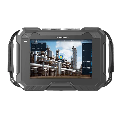
- Turn on the CRY8124 and select the vacuum/leak scenario.
- Set the acoustic imaging band to 20–40 kHz.
- Adjust the imaging threshold (-40 dB to 120 dB) based on on-site conditions to reduce background noise from fans, cutting machines, and vacuum pumps.
- If ambient noise is high, enable focus/beamforming mode to further suppress environmental noise.
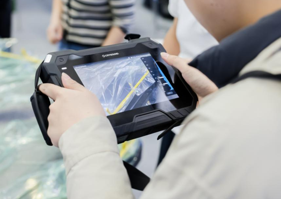
On-Site Leak Scanning Workflow
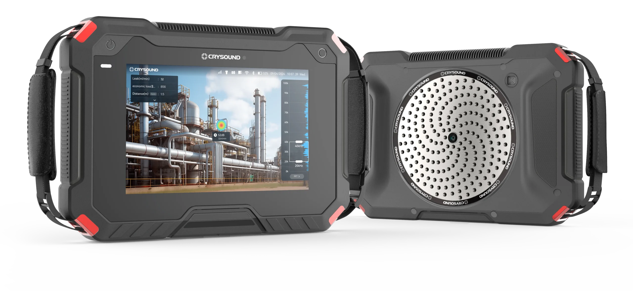
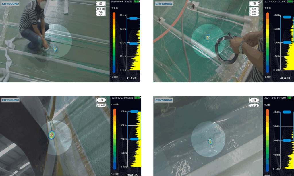
During inspection, the operator walks along key areas—such as the pressure side (PS), suction side (SS), the main-spar region, and around the root preform—while holding the CRY8124 Acoustic Imaging Camera. When a leak is present, the device overlays an acoustic “cloud map” on the live video feed, helping pinpoint the leak location and reducing repeated manual checks.
Measured Impact (Customer-Reported)
After introducing the CRY8124 Acoustic Imaging Camera, the average vacuum bag check time per blade dropped from 30+ minutes to around 10 minutes (about a 70% reduction in check time). The customer also reported annual cost savings exceeding $10,000 by reducing rework and scrap.
How a 10-Minute Vacuum Bag Check Is Achieved
The CRY8124 Acoustic Imaging Camera is designed for fast scanning across common blade inspection zones (PS/SS surfaces, main spar region, and the blade root). It provides a visual indication of leak location and relative leak severity, while using frequency filtering and beamforming to work in noisy production environments. With a high-density microphone array (up to 200 microphones, depending on configuration) covering 2 kHz–100 kHz, the system can capture ultrasonic components from small leaks and render them as an intuitive acoustic image.
If you’d like to learn more about acoustic imaging for vacuum leak detection—or discuss your blade process and inspection targets—please use the “Get in touch” form below. Our team can share recommended settings and an on-site workflow tailored to your production conditions.
In acoustic design and noise control, a material’s acoustic impedance characteristics are a key factor in determining “how it sounds.” By measuring parameters such as the absorption coefficient, reflection coefficient, specific acoustic impedance, and acoustic admittance, we can not only quantify a material’s ability to absorb and reflect sound, but also evaluate its performance in real-world applications—such as room reverberation time, noise-control effectiveness in equipment, and the acoustic comfort of products like automobiles and home appliances. Accurate acoustic impedance testing gives engineers solid evidence for material selection, structural optimization, and acoustic simulation, dramatically reducing trial-and-error costs and shifting acoustic design from experience-driven to data-driven.
Advantages of the Transfer-Function Method
Among the many acoustic impedance measurement methods, the transfer-function method is widely used thanks to its fast testing speed, high accuracy, and broad applicable frequency range. By placing two microphones inside an impedance tube and using the sound-pressure transfer function, one can back-calculate parameters such as the absorption coefficient, reflection coefficient, and specific acoustic impedance—without complicated sound-source calibration or overly idealized assumptions about the sound field. Compared with the traditional standing-wave ratio method, the transfer-function method depends less on operator experience, delivers more stable low-frequency measurements, and is easier to automate and post-process, making it well suited for R&D, material screening, and high-throughput quality inspection in industry.
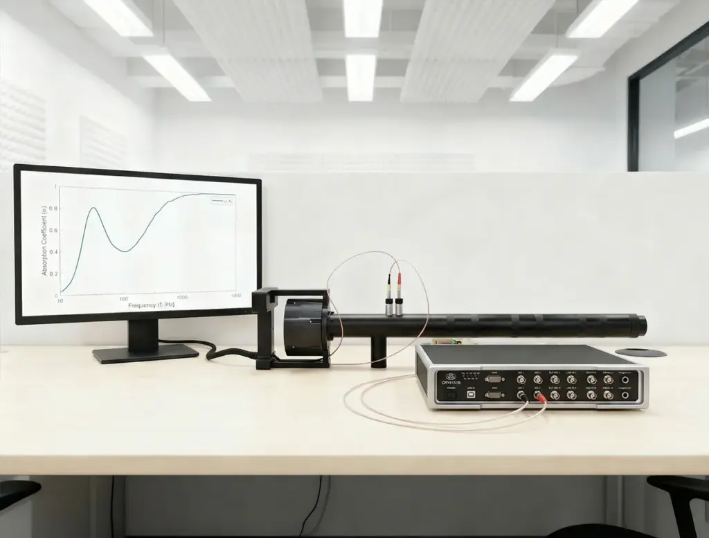
CRYSOUND Integrated Test Solution
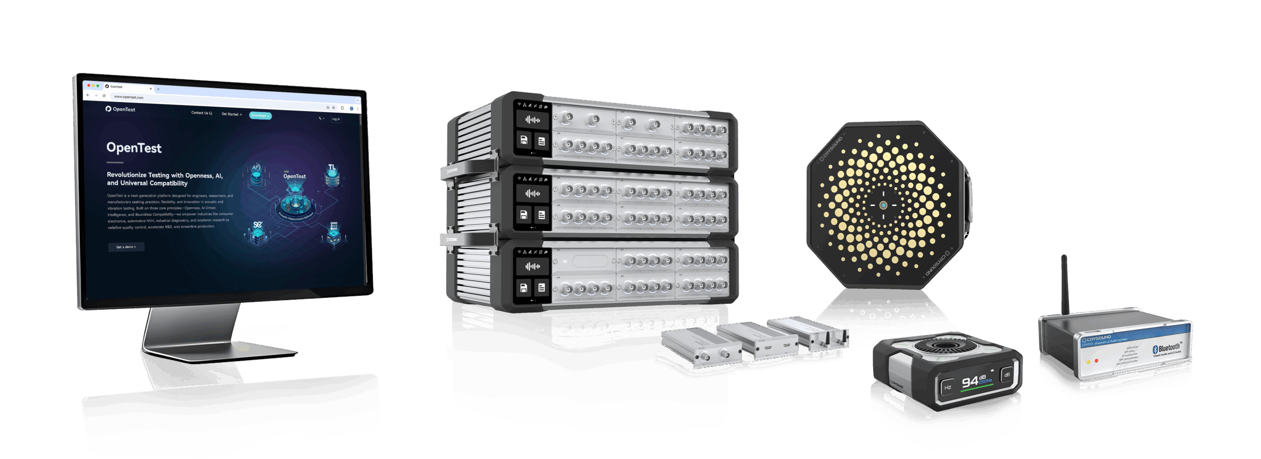
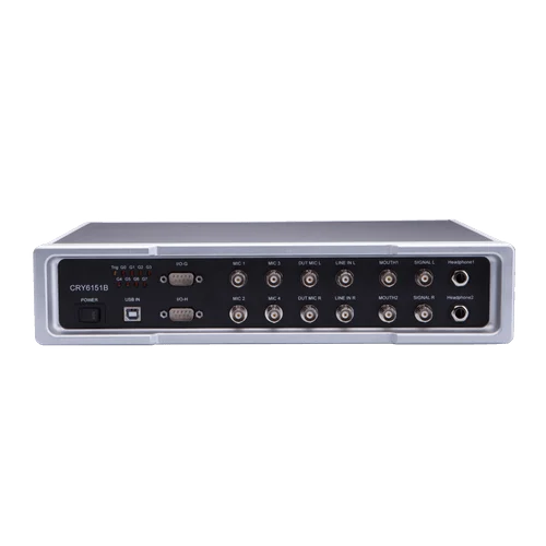
CRYSOUND provides a complete acoustic impedance testing solution. Built around the CRY6151B data acquisition unit, and combined with our in-house algorithms plus testing software and an impedance-tube hardware system, it delivers an integrated workflow—from equipment calibration and data acquisition to parameter calculation and report generation.
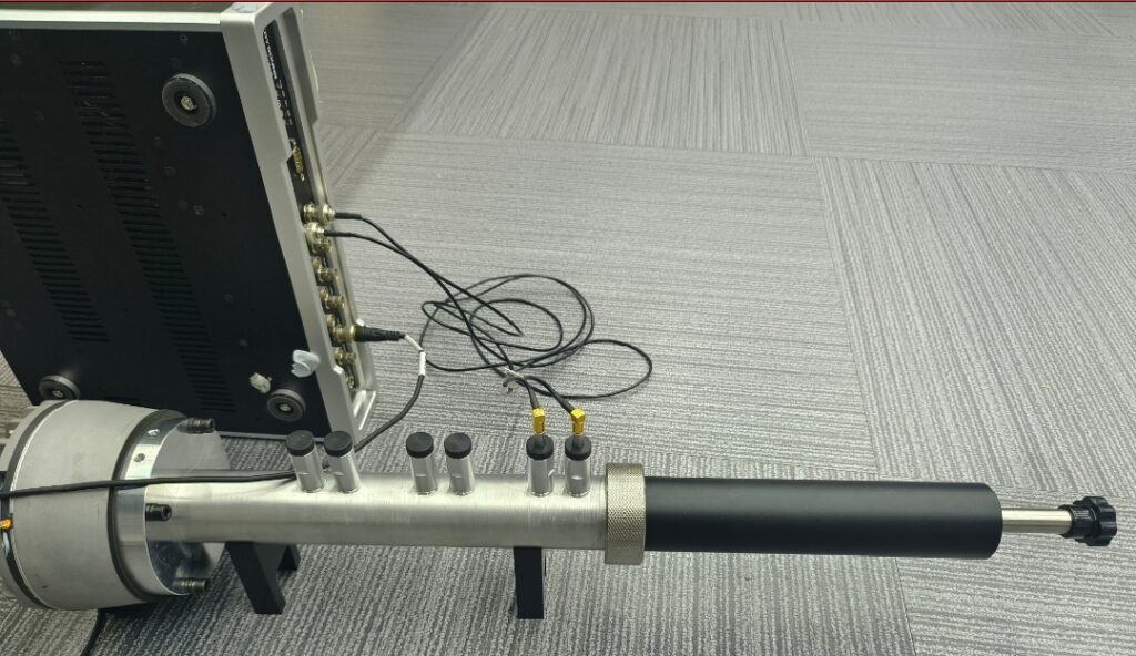
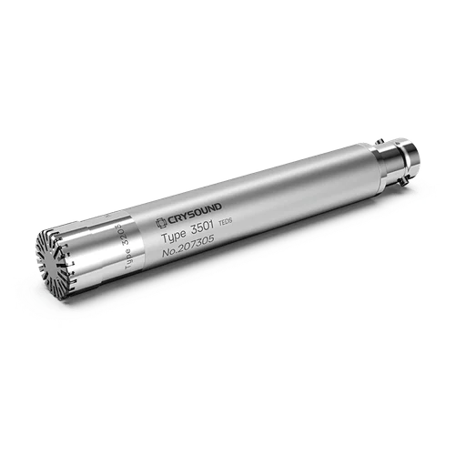
In terms of hardware configuration, we use a measurement chain optimized specifically for acoustic impedance testing. At the front end, two 1/4-inch pressure-field measurement microphones (CRY3402) are deployed. While ensuring a wide frequency range and wide dynamic range, they maintain excellent linearity and stability under high sound-pressure levels—making them ideal for precise measurements in the high-SPL sound field inside an impedance tube. At the back end, a CRY6151B data acquisition unit handles signal acquisition and output control, featuring low noise floor, stable output, and a clean, straightforward interface and operating logic.
On the software side, we provide a complete workflow covering calibration, measurement, analysis, and reporting—making the tedious yet critical steps in acoustic impedance testing both meticulous and easier for users. Before testing, the software guides users through input/output calibration to ensure the gain and phase of the excitation output and acquisition channels are under control. It then performs a signal-to-noise ratio (SNR) check, automatically evaluating whether the current test environment and hardware configuration meet the conditions for valid measurements, avoiding wasted time under low-SNR conditions.
To match the characteristics of the transfer-function method, the software integrates transfer-function calibration and dual-microphone acoustic-center distance calibration modules. Through dedicated calibration procedures, it automatically corrects inter-channel amplitude/phase errors and microphone acoustic-center position offsets, reducing high-frequency ripple and computational error at the source. It also supports flange-tube calibration, compensating for leakage and geometric deviations at flange connections so that reliable absorption-coefficient and acoustic-impedance results can still be obtained even under conditions close to real-world use. The entire workflow complies with the requirements of GB/T 18696.2-2002.
During actual measurements, the software supports multiple excitation types, including random noise and pseudo-random noise for rapid wideband scanning, as well as single-tone signals for precisely locating resonance frequencies and analyzing the relationship between impedance and sound speed — useful for material mechanism research or fine tuning. After the test, the data can be displayed in multiple band formats, and curves from different samples or operating conditions can be compared within the same interface. Users can view key parameter curves such as the absorption coefficient, reflection coefficient, and specific acoustic impedance, and can also automatically generate a test report that includes measurement conditions and result plots, greatly improving the efficiency and standardization of acoustic impedance testing.
Overall, acoustic impedance testing is both a “magnifying glass” for understanding a material’s acoustic properties and a “ruler” for translating acoustic design into engineering reality. With an optimized hardware chain (CRY3402 microphones + CRY6151B data acquisition unit) and an integrated software platform that combines calibration, measurement, analysis, and reporting, we aim to make acoustic impedance testing—once a highly specialized and complex task—controllable, visual, and repeatable, truly supporting product R&D, quality control, and acoustic-experience improvement for enterprises.
In day-to-day acoustic measurements, it’s common to hear: “Insert the measurement microphone into the calibrator, press the button, and the microphone is calibrated.” From an engineering and metrology perspective, that wording is an oversimplification. To place a sound calibrator correctly in the measurement chain, we should start with what it generates—and what it can (and cannot) verify.
Core Function of a Calibrator
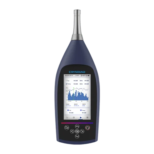
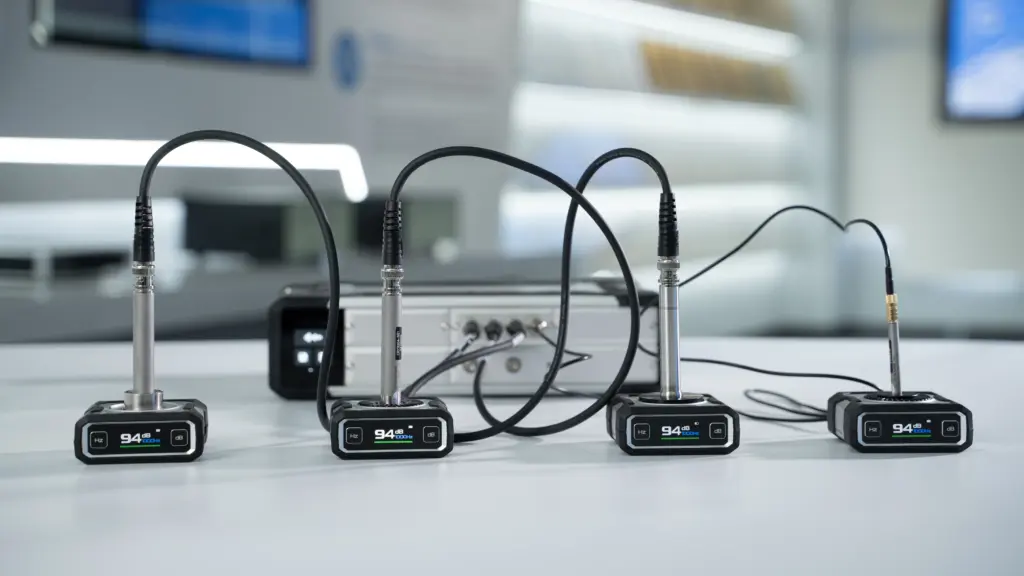
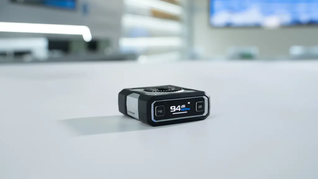
A sound calibrator is essentially a reference sound source that generates a stable, known sound pressure level (SPL) at a specified frequency—typically 1 kHz (and 250 Hz on some models). Depending on the model, the nominal level is often 94 dB or 114 dB.
During use, you compare the calibrator’s nominal SPL with the reading of the entire measurement chain (microphone + preamplifier + front-end or sound level meter) to confirm whether the indicated value matches the reference.
In other words, a calibrator is primarily an on-site verification tool rather than a device that “calibrates” (adjusts) the microphone itself. It helps you answer one practical question: for a known SPL at a known frequency, is the system reading correct?

Relationship Between the Calibrator and the Measurement Microphone
Structurally, a calibrator mainly provides a controlled acoustic field at the microphone diaphragm. It does not change the microphone’s intrinsic characteristics—such as sensitivity, frequency response, linearity, dynamic range, or self-noise.
If the microphone or preamplifier drifts due to aging, mishandling, temperature/humidity exposure, or mechanical shock, the calibrator can reveal the deviation—for example, a consistent offset from the nominal level.
But the calibrator cannot “fix” the microphone. If the deviation is abnormal, unstable, or growing over time, you typically troubleshoot the chain (fit/seal, adaptor size, connector, cable, preamp gain, settings) and, when necessary, send the microphone and/or calibrator to a laboratory for calibration or service.
Understanding “Calibration” from a Metrological Perspective
In acoustic metrology, “calibration” generally means comparing a device to a higher-level reference standard and documenting its deviation (and, where applicable, a correction factor) with traceability to national or international standards.
For measurement microphones, a rigorous calibration is typically performed in a controlled laboratory environment, using reference microphones and equipment that comply with relevant standards (e.g., IEC 60942 for sound calibrators and the IEC 61094 series for measurement microphones). It commonly includes multi-point testing across conditions and an uncertainty statement.
In the traceability chain, a handheld sound calibrator is mainly an on-site step used to: 1) perform quick checks before and after measurements, 2) record drift during use, and 3) support decisions on recalibration or service.
Therefore, it’s more accurate to say: you are using a calibrator to verify the measurement system on-site—not completing a formal microphone calibration.
Also note: the calibrator itself is part of your traceability chain. To keep the check meaningful, ensure the calibrator has a valid calibration certificate and is used within its specified environmental range.
Summary
A calibrator is a very important on-site comparison tool in the measurement chain. It can:
- Provide a standard sound pressure level signal for measurement microphones
- Help engineers quickly check whether the measurement system is operating in a reasonable state
At the same time, it must be clearly understood that:
- The calibrator does not directly “calibrate” or repair the microphone itself
- Formal microphone calibration must be performed in a standard acoustic laboratory and must follow metrological specifications and procedures
In engineering practice, only by clearly distinguishing between “on-site verification” and “laboratory calibration” can we both efficiently carry out daily testing and ensure that measurement data are accurate and metrologically traceable.
You are welcome to visit www.crysound.com to learn more about microphone functions and hardware solutions, or contact the CRYSOUND team of demonstrations and application support.